VFRDiscussion ARCHIVE / READ-ONLYREAD-ONLY

Yoshi Style Velocity Stacks

59 posts Started 1 Apr 2015 Last recovered post 7 Mar 2016 Wayback Machine snapshot 11 Mar 2016

#1

Whilst researching variable velocity stacks, I stumbled across Yoshi's dual stacks.  Then whilst playing with some spare stacks I had an idea, that I could create something similar.

I had previously reduced the standard stacks by 30mm as part of the Big Airbox mod I did last year.

So here is the result of my tinkering. Not run the bike yet, but will test tomorrow. This is only possible because I did the Big Airbox mod, which increases the clearance in the box, these stacks would not fit under the standard airfilter position.

Upper stack

[image: upper stack.jpg]

Old & New

[image: old and new stack.jpg]

As above illuminated for effect

[image: old and new stack illuminated.jpg]

A full set

[image: new stack full set.jpg]

Enjoy

#2

It  will be interesting  the  affect  on  your   low  rpm  range  but  mid  and  high  should   be  better .


#3

You should see the ST1300 airbox. Curved stacks going in all directions! Crazy looking, but I guess they were trying to get length but still have each in it's own quadrant?


#4

I  guess you left  the  gap  at  the  bottom  to  help  at  low  rpm .   


#5

I  guess you left  the  gap  at  the  bottom  to  help  at  low  rpm .   

Other way around I think... low rpm air flow through the whole dual stack and the gap at the bottom will allow air flow at high rpm when flow through the dual stack begins to get impeded.

... or are you trying to capitalize on the Bernoulli's principle of pulling additional air in from the sides by the decreased pressure of the fast flowing center air column???


#6

I  guess you left  the  gap  at  the  bottom  to  help  at  low  rpm .   

Other way around I think... low rpm air flow through the whole dual stack and the gap at the bottom will allow air flow at high rpm when flow through the dual stack begins to get impeded.

... or are you trying to capitalize on the Bernoulli's principle of pulling additional air in from the sides by the decreased pressure of the fast flowing center air column???

Hmmm  always  thought  the  longer  velocity  stack  slow  down  the  charge  of  air  at  low  rpm's.


#7

I  guess you left  the  gap  at  the  bottom  to  help  at  low  rpm .   

Other way around I think... low rpm air flow through the whole dual stack and the gap at the bottom will allow air flow at high rpm when flow through the dual stack begins to get impeded.

... or are you trying to capitalize on the Bernoulli's principle of pulling additional air in from the sides by the decreased pressure of the fast flowing center air column???

Hmmm  always  thought  the  longer  velocity  stack  slow  down  the  charge  of  air  at  low  rpm's.

Everything is a compromise... the shorter the velocity stacks the higher you move the volumetric efficiency (VE) rpm, within reason that is, you can make them too short.  Longer velocity stacks improve low end torque by improving the air charge flow at lower velocity, shorter give more top end horsepower...  that's one reason why our bikes have the flapper and snorkel; longer snorkel to improve VE at lower rpms and the flapper to shorten the path when the rpms climb... that's part of the theory anyway.

Variable length velocity stacks start out long and shorten when the rpms pass a certain threshold...


#8
Keen to see the results of this. I thought the big air box was brilliant, so looking forward to this next step.
#9

Here's a pic from the KTM forum where I stumbled on the concept. The most impressive part is the midrange gains :)

[image: Superduke-stacks.jpg]

http://www.ktmsmt.co...php?f=13&t=3299  Page 7, page 13, page 17, page 18, page 27, page 33, page 48


#10

Ran the bike at lunch time & it starts & when warm revs quicker than yesterday, so appears to have improved the torque curve. Revs to the redline pretty quickly. Will try to get out for a run in the next couple of days.


#11
Only way to tell is before and after dyno runs....if you have the luxury of time and cash...
#12

Well I have the luxury of having done dyno runs every year after I have made mods, you will find them posted elsewhere on this site. Power wise its gone from 95hp as std, to 99, to 102, then 107 with my cams & 112 with the big airbox/short stacks mods last year. Hoping the dual stacks & TBR will push it over 120 with no low/mid range loses. Good or bad once I've tweaked the fuelling, I will post a dyno chart with the results.


#13

Hey Mohawk, neat work!  I've been pondering utilizing the flapper circuitry to actuate some sort of variable length velocity stack... but a fixed version accomplishing the same task would be much preferred.  

What spacing between the stacks are you using and do you plan to test different spacing to optimize air flow?


#14

Hey Rush2112, great minds & all that. I started off looking at variable length stacks & I was also planning on using the flapper actuator to control it !

Then I found the KTM site & the Yoshi stacks.

So based on the Yoshi design, whch the GSXR guys claim makes more low/mid range torque with no losses up top, I copied that idea. The Yoshi dual stacks inner stack has the same diameter as the outer & its base is flush with the top of the outer stack. So mine are positioned the same.

Dyno will tell. With standard stacks, mine made a peak torque of 57.5lb/ft, with the short stacks & big airbox mod, this fell to 54lb/ft, but stayed higher longer to produce more HP. If these stacks can both create more torque and say put the peak back to around 58lb/ft & still hang on at higher revs, then it will improve the HP too. Not to mention the TBR system should help boost high rpm flow as well.

I need to raise max rpm torque from the current 48.5 for 112hp, to 50.5 to get 120hp !  I'm hoping the new combined setup will do it.


#15

Excellent ideas!!!  

Do you have a link to the earlier Yoshi work?  I tried a search for it and failed... I'd like to read the original work too...


#16

Just do a search for Yoshimura dual stacks


#17

Ohhhh!!!  I thought you meant our Yoshi...  

I was looking in the VFRD archives...

duh, my bad


#19

Now that is a neat video, explains so simply how pressure waves work. Pity they simplified it to one pulse, when most bikes are tuned (or not) to the 4th reflection, each one weaker than the previous. This is due to the inlet track length being too short for a 1st or 2nd wave reflection, sometimes the 3rd wave chimes in at lower RPM, but mostly at higher RPM its the 4th wave. Just imagine that Blue wave racing up & down 3 times, with the inlet valve closed & losing intensity then arriving on the 4th reflection as the inlet opens.

I've not managed to find anything other than circumstantial info that these work, so will sort my fueling then get a dyno run to compare with previous runs & see what happens.


#20

Still tweaking the fuelling, it was so rich it was crazy. So now almost sorted. Weather crap here at the mo, so will try to get dyno run next week to check the current power curve against the last ones. Will use the same dyno as before.


#21

Still tweaking the fuelling, it was so rich it was crazy. So now almost sorted. Weather crap here at the mo, so will try to get dyno run next week to check the current power curve against the last ones. Will use the same dyno as before.

Rich?!?  We want more air not less... was it a fueling adjustment or related to the dual stacks?


#22

The dyno place I use would not let me run it with my computer attached to map the RB Racing for H&S reasons, no public in the dyno room ;(. So I've fitted a wideband AFR meter, so been manually tuning the fuelling using that. So it does not have a Lambda sensor, so defaults to very rich ECU map, anywhere the Lambda should control fuelling. So below 7Krpm, above that the fuelling is near perfect, though I can't spend much time at high RPM in the higher gears for obvious reasons. So I'm fixing the lower rpm fuelling at the moment.

The dyno run will be used to confirm the higher rpm fuelling as well as the whole power curve !


#23

OK, so got the lowend fuelling reasonable & took the bike for a power run on the same dyno as always, they do racing & race bikes, so the guys know what they are doing, so without further ado here's the results after adding the TBR full system but with my Delkevic mid length silencer & of course with the Yoshi style dual stacks in place.

[image: image.jpg]
Power & Torque

[image: image.jpg]
Fuelling

As you can see the power curve smoothed right out with the Yoshi style stacks & peak is up 6hp from the TBR. I may strip the Yoshi stacks out & adjust the fuelling then try again. But a 25% power hike is not to be sniffed at :)


#25

NICE!!!

I'm soooooooooooooooooooooo jealous....

:fing02:   :beer:   :cheerleader:   :wheel:


#26
Dimsport have fixed the missing rev extend, so I'm calling it 120hp :)
#27
Hell yeah, nice work.
#28

Hey Mohawk

Nice looking graph and I do like the stacks.

What exactly were the stacks off that you used?

Cheers

Phil


#29

You're edging towards 870cc output levels there. Very impressive!


#30

Hey, sorry, I just realised that they are the stock trumpets.

Should have looks more closely.


#31

120hp on a 396lb VFR  "WOW"  GREAT WORK!!!!!!!


#32

This IS really cool!  


#33

Hey, sorry, I just realised that they are the stock trumpets.

Should have looks more closely.

Yep, originally with the big airbox mod, I cut a standard set off flush with the mushroom lip & then pinned & filled with liquid metal around the mount holes, then filled the rest with car filler. sanded the bottom flush & added double sided sticky tape to locate them before screwing in place.

The Yoshi style second set just mount on longer screws with nyloc nuts to keep the clearance at the bottom & one at the top tightened just enough to still allow the screw to turn to locate them.


#34

I've been working on the dual velocity stack scenario, similar to what Mohawk outlines in this post, on my 825 Gen6/5.

What I've ended up using for the short stacks are Weber 40mm DCOE 20mm long aluminium ones and them mounted the standard VFR short stacks over the top.

Here are some shots of what it all looks like.

[image: 20150812_123416.jpg]

[image: 20150812_123329.jpg]

[image: 20150812_123127.jpg]

[image: 20150812_123214.jpg]

I've used fixed length aluminium tube spacers to set the height of the secondary stack and positioned the bottom of the VFR stack level with the top of the Weber stack.

On first testing, the bike didn't feel that crisp in the mid range so I shortened the spacers by 2mm.

What a difference!

Mid range well covered and nice even power delivery from 3500 up.

Thinking I might take another 1mm off the spacers and see what effect that has.  I can always add a washer to bring it all back.

Cheers

Phil


#35

Wow. If it works half as good as it looks everybody will be doing it.

(Said the guy with carbs...)


#36

Highside that is some nice looking work there!


#38

Sweet! Very nice... :cool:   :beer:


#39

As always... Nice work Phil!  I'm very interested in the final spacing/alignment of the primary and secondary VS.  

Did you go with the 40mm due to your increased displacement or was it related to availability?  What are the stock VFR VS 36mm?... 38mm?  

Any observed increase in the RapidBike fueling adjustments to indicate a measured increase in air charge flow?


#40

there is some brilliant work happening on here at the moment.

I cant big bore a motor, but i can make these stacks, i reckon.  And you wont see them ,so when its a bit uglier than phils' work, it wont matter.

Big air box and these stacks are going on my list.


#41

Thanks guys.

Rush2112, to answer your questions.

The airbox base bores, where they fit to the throttle bodies are 40mm diameter, hence why I went that way.

I have flowed the throttle bodies, both sides of the butterflies, and matched the throttle bodies to the airbox base and the aluminium trumpets.

What I did was made up a dolly to align the trumpets to the airbox base and then pinned the trumpets to the airbox with 3mm spring pins at each end.

This way the trumpets are permanently located to the airbox.

Calculating the trumpet lengths for my cam timing etc. ended up with the following:

Centreline intake port length = 100mm (to step in rubber isolator)

Throttle body length = 75mm

Airbox base thickness = 6mm

So intake runner length to top of airbox base (where trumpets will sit) = 181mm

My calcs for a total runner length for 8000 RPM = 251mm

And for 10000 RPM = 201mm

That would be a trumpet of 70mm for 8000 RPM

And a 20mm trumpet for 10000 RPM.

The overall length of the short standard VFR trumpets is 52mm

So with that length, it all worked out if I could get a 20mm trumpet.

All that I could find was the 25mm ones that I ended up with (sorry I miss typed the original post showing 20mm) so it will have pushed the tuned runner RPM down by about 500.

I know that was a bit of a long winded explanation but there is some pretty intense calculation goes in to this.

Cheers

Phil


#42

Thanks guys.

Rush2112, to answer your questions.

The airbox base bores, where they fit to the throttle bodies are 40mm diameter, hence why I went that way.

I have flowed the throttle bodies, both sides of the butterflies, and matched the throttle bodies to the airbox base and the aluminium trumpets.

What I did was made up a dolly to align the trumpets to the airbox base and then pinned the trumpets to the airbox with 3mm spring pins at each end.

This way the trumpets are permanently located to the airbox.

Calculating the trumpet lengths for my cam timing etc. ended up with the following:

Centreline intake port length = 100mm (to step in rubber isolator)

Throttle body length = 75mm

Airbox base thickness = 6mm

So intake runner length to top of airbox base (where trumpets will sit) = 181mm

My calcs for a total runner length for 8000 RPM = 251mm

And for 10000 RPM = 201mm

That would be a trumpet of 70mm for 8000 RPM

And a 20mm trumpet for 10000 RPM.

The overall length of the short standard VFR trumpets is 52mm

So with that length, it all worked out if I could get a 20mm trumpet.

All that I could find was the 25mm ones that I ended up with (sorry I miss typed the original post showing 20mm) so it will have pushed the tuned runner RPM down by about 500.

I know that was a bit of a long winded explanation but there is some pretty intense calculation goes in to this.

Cheers

Phil

Many of us love the details and those that don't will skip over it anyway... feel free to be as long winded as you like  :wink:

Cheers

Russ


#43

Did some further testing today and took another 1mm off the spacers lowering the top stacks further into the bottom ones.

Interesting findings, i must say.

By my "butt" dyno the roll on was really smooth but it lacked that bit of a bang.  Just not sharp.

It also seemed to knock the top end around a bit.

So, I've added the 1mm back in and it is back to as before.

From this I would have to say that the gap between the 2 stacks is quite critical and probably the only way to obtain the optimum distance would be with quite a bit of dyno time, or lots of road time.

Also, going with Mohawks idea of the double nut arrangement, or multiple Nyloc nuts so as you have infinite adjustment is probably the way to go getting the correct spacing, then make the fixed spacers after that.

I'll update the post once I have more info.

Cheers

Phil 


#44
Hey Phil, great to see this, somehow missed it the first time around. I must remember to add watch to my own threads ;)

Looks good, interesting the difference you got with different settings. So with your minus 2mm where does that place the upper stack relative to the lower one ?

Mine are set level, so bottom of upper is level with top rim of the bottom part. The 10mm high mushroom lip, gives a tuned length of 195mm measured with a piece of wire to the lowest edge of a closed intake valve. The 5th gen stacks are all the same size at 60mm, so the low end tuned length is 255mm.

You can work out your own 4th reflection wave dynamics here http://www.velocity-...calculator1.htm

IIRC std cam timing is 225 degrees, with a tuned length of 235mm for a 4th wave peak at 8600rpm.

If you check out my last dyno torque line, you will see that the long & short stack waves work perfectly, with long peak at 8k RPM & short peak at 10k RPM, which gives a totally flat torque curve across that 2000 rpm range. So it does what it's supposed to.

Have fun.
#45

You guys (Mohawk and HighSideNZ) work for NASA? European Space Agency? Love reading your threads, keep it coming. 


#46

Hey Chris

As the internal diameter of my lower stacks is 40mm I've now got mine set 2mm below the top.

Started off with them level and as I mentioned in the earlier post dropped them by 1mm, then 2mm, then 3mm and lastly back to 2mm

I'm sure that it is all to do with the area between the 2 stacks and the impedance to flow that it creates.

Too large a gap and the flow takes the path of least resistance and instead of air column going via the long path it takes a shortcut between the stacks.

I've just put my other airbox back on today so as I can get some better comparisons between the Yoshi style and what I was running previously with Yamaha R6 trumpets.  2 short ones on the front and 2 long ones on the rear.


#47

You guys (Mohawk and HighSideNZ) work for NASA? European Space Agency? Love reading your threads, keep it coming.

If we did, we'd have been to Mars & back by now ;)

In reality, I'm just an average Joe with a high IQ (who knew ?) from a poor background, that left school at 16. I discovered I have a talent for working stuff out & fixing things. More so if I have an interest. My dad was an Army mechanic when I was very little, so I've worked on vehicles since I was old enough to pass a spanner :)

But bikes & aircraft have always been my passion, can't afford a plane, so here we are !

Glad someone enjoys our tinkering.
#51

Mohawk can you confirm you complete bike setup? Exhaust, Cams, Intake?

What is the best setup for the dual velocity stacks?

4 stock "short" stacks mounted to the airbox?

4 stock "short" stacks mounted ?mm below the tops of the 1st units

Air box cut as per "big airbox mod" thread

Very impressive power gains and weight losses!!


#52

Bigger is not always better... my story...

My friend Stephen called long distance from England because he just
installed a $900.00 HRC air box on his RC45 and saw 120HP on the
dyno... mmmmm... together we wondered if the stock box be modified???

gallery_3131_51_178065.jpg


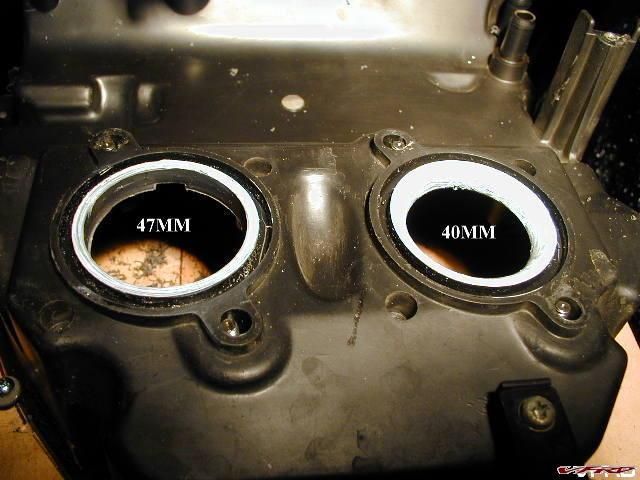
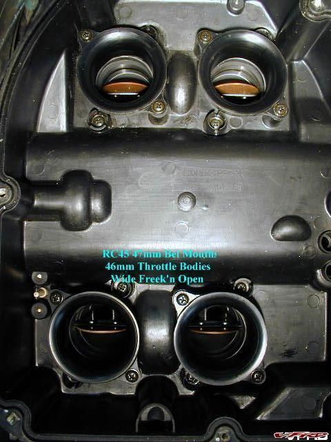
We found that stock RC45 throttle bodies are 46mm but the air box was
restricted to 40mm... no problem... I'll bore the air box out to 47mm
on the milling machine...
gallery_3131_51_12643.jpg


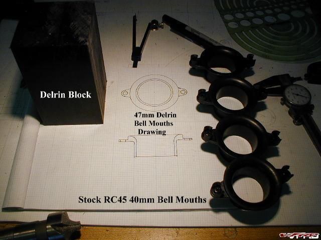
I drew up plans for 47mm bell mouth based on the stock 40mm bell
mouths and purchased a block of black Delrin...
gallery_3131_51_61101.jpg


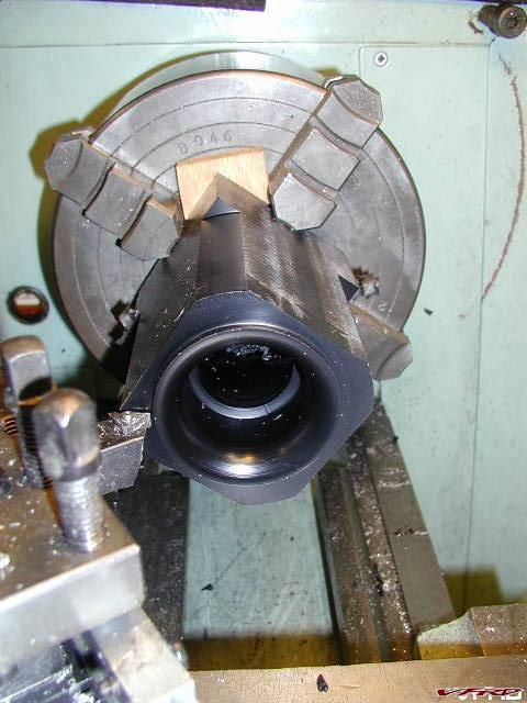
I'm not happy doing repetitious work but I labored long hours to
machine 4 each bell mouths with my best accuracy...
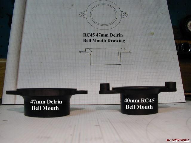
gallery_3131_51_60103.jpg


Don't you love when a plan comes together especially if it turns out
perfect???
gallery_3131_51_73307.jpg


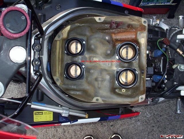
Now I had an unrestricted air box with my own 47mm bell mouths... it
was the best I could do to replicate HRC $900.00 air box... not to
mention I wanted to keep  my home made K&N filter...
gallery_3131_51_44329.jpg


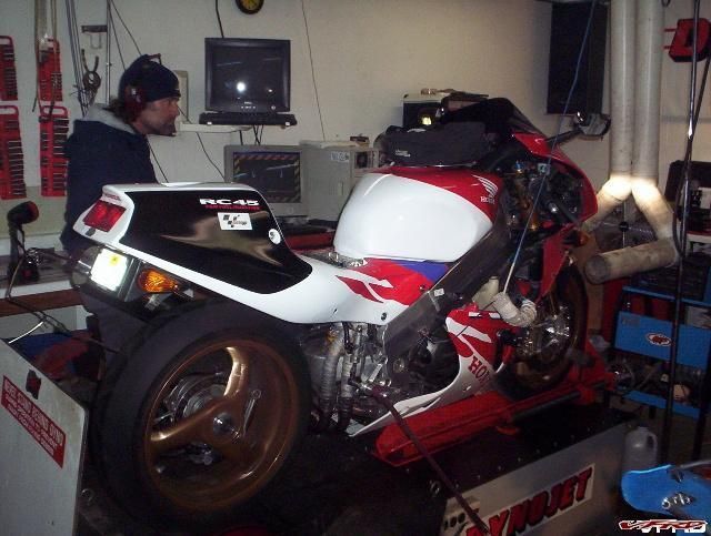
Time to put the Mod to the test... this is Dave at Chandelle
Motorsports...
gallery_3131_51_181600.jpg


No joy... I lost 1.8HP on the dyno... so bigger is not better in this
case... a whole week worth of work shot down in flames... it seems
Honda got the intake velocity right for a stock  pipe after all... air
boxes are like tuned instruments... alter the holes and the tune
suffers...


#53

What did you do to compensate for the necessary fueling changes?


#54

Mohawk can you confirm you complete bike setup? Exhaust, Cams, Intake?
 
What is the best setup for the dual velocity stacks?
 
4 stock "short" stacks mounted to the airbox?
4 stock "short" stacks mounted ?mm below the tops of the 1st units
Air box cut as per "big airbox mod" thread
 
Very impressive power gains and weight losses!!

Engine is stock, apart from the following;-
My own spec cams
CoIl on Plug, from cbr1000rr 2007 model
Matched throttle body to head rubbers
TBR full exhaust, with Delkevic mid length Ti silencer
Big airbox mod with ramair intake
Velocity stack tops (the round lips) mounted straight on to airbox base, for 10mm stack height. Plus secondary stacks, base flush at 10mm from airbox.
Rapid Bike Racing fuel controller with one MTB O2 sensor.

What did you do to compensate for the necessary fueling changes?

Still running the single MTB, bottom & top end are fine, mid range from 5500-7500 still being tuned, but winter interrupted play :(


Hey Larry, you should try my dual stack idea with those big intakes I think it would help your fuelling !
#55

Hey Larry, you should try my dual stack idea with those big intakes I think it would help your fuelling !

Mr.RC45 fueling is not the problem... my air box will remain stock
because our air box works like a finely tuned instrument... any wild
ass guess mod disrupts this highly engineered resonant to where to
you're producing nothing but sour notes... The airbox inlet tubes, or
“horns”, are specifically designed to provide a resonance that can
increase the total airflow by up to 10-15%. Second guessing these can
cause the engine to loose power and increase the intake noise as in my
case...


#56

No not you mohawk, I was asking busy little shop. I know you are running Rapid Bike, so you have the ability to make air flow changes/mods and then see if the AFR is going richer or leaner. That way you can tell if the corresponding mod is pulling in more air/demanding more fuel or not. I know you put a lot of thought and calculations into the design of the velocity stacks and they are not "wild ass guess mods". On the other hand, I don't know why busy little shop was opening his air inlets from a conservative 40mm to a gigantic 47mm with out any ability to make the necessary fueling changes. I am not surprised the rc45 ran sour after doing that, but I am surprised that he feels the need to compare his untuned wild ass guess mods to your highly thought out and tunable mods. 


#57

Hmmm, I can't helper wonder what I might see with my 5th gen. I got some great dyno numbers,  and now see I need a full exhaust system to make it even better,  but this stack thing sort makes sense..  ;)  what goes in, gota come out though.  


#58

Hmmm, I can't helper wonder what I might see with my 5th gen. I got some great dyno numbers,  and now see I need a full exhaust system to make it even better,  but this stack thing sort makes sense..  ;)  what goes in, gota come out though.  

Unless you are on the confirmed buyer list for the Tyga headers, good luck finding a real full system.


#59

LOL  yea yea yea...  we'll see when TYGA gets it together what comes of it.  I'm praying it works out, but??? 


End of thread · 59 posts recovered Wayback Machine snapshot 11 Mar 2016