Hi all. So the vf500 I picked up has had a lot of electrical hacking done to it. Im getting a new ignition as the key was lost and have been using a bridge to start and run it.
The big issue among others is that the radiator fan won't turn on. I'm hoping that it has something to do with the ignition switch? It's not burnt out, I ran lines to the battery and it works.
There are wiring coming out of either side of the handles, initially I thought them to be for the indicators but when I split them apart the bike would turn over.
Im not even sure what this connection is for, rear turn signals?[image: IMG_20190812_195732474.thumb.jpg.37b8de7b2227588959c64ea8ab809f15.jpg]
The panel has been ground down and a lot of the connectors have been spliced[image: IMG_20190812_195752370.thumb.jpg.ab817268fb86fc5c5ce0c2042687134a.jpg]
What is the history of this bike? Why is its wiring "hacked"?????
If you get yourself the proper wiring diagram, you should then be able to work out what's what via the colour coding.
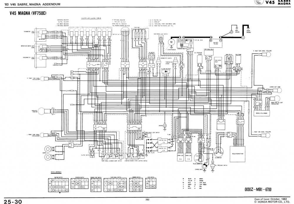
I'm sure that 3 pin White connector with the Blue, Black and White wire is for the Fuel Cuttout Relay, which is probably bypassed.
The Green and Light Green wires in your left hand are most likely the Horn Switch wires.
The pair of wires on the right hand side the Green/Yellow and White/Green is the front Brake Switch.
Your wires at the front of the bike are most likely your Blinkers and Position light. Left Blinker is Orange, Right Blinker is Light/Blue, Position Light is Brown, the Green is the ground return.
Got this info from a Magna V45 VF750C drawing (see attached) probably similar to your bike, couldn't find anything exactly for your model 1985 VF500.
There are wiring coming out of either side of the handles, initially I thought them to be for the indicators but when I split them apart the bike would turn over.
Assume you mean "bike would not turn over" = probably clutch switch wiring.
What is the history of this bike? Why is its wiring "hacked"?????
If you get yourself the proper wiring diagram, you should then be able to work out what's what via the colour coding.
I'm sure that 3 pin White connector with the Blue, Black and White wire is for the Fuel Cuttout Relay, which is probably bypassed.
The Green and Light Green wires in your left hand are most likely the Horn Switch wires.
The pair of wires on the right hand side the Green/Yellow and White/Green is the front Brake Switch.
Your wires at the front of the bike are most likely your Blinkers and Position light. Left Blinker is Orange, Right Blinker is Light/Blue, Position Light is Brown, the Green is the ground return.
Got this info from a Magna V45 VF750C drawing (see attached) probably similar to your bike, couldn't find anything exactly for your model 1985 VF500.
Grum, you are a fountain of information on VFRs of all sorts. V glad you are one of us!
Thanks a bunch everyone. I picked up an 85 and an 86 for 700. My friend is trying to get the 86 going (carb has been completely dismantled) I'm working on the 85. Biggest concern is electrical right now for me. We have a crymer manual I'm just neither a sparky nor a mechanic haha. Loving the bike though!
Dutchy is correct. I've skid my lid so much I have to look at which way my shoes are pointing to tell if I coming or going. :wacko:
But NO lid skidding since I've taken several Advanced Rider Courses at the Dakota County Technical College (DTCT) track. (Knock Wood - in my case I just tap my head) no skidding for the last few years. :woohoo:
like grum said, you'll get nowhere without a wiring diagram and observing color codes. in addition, a volt/ohm meter is almost a necessity for doing any serious electrical work.
End of thread · 12 posts recoveredWayback Machine snapshot 14 Dec 2019