Here is my version of "beef up 'dem 'dare wires!".
This mod/upgrade is meant to fix any under OR overcharging problems, and improve the Regulator/Rectifier (R/R) to battery charging wires and grounds. It was done to a 2002 VFR but years 2002-2005 should have the same wiring harness.
This was my 30 Amp fuse wire problem:
[image: gallery_11167_3051_30043.jpg]
Toasted 30 Amp fuse wire
Followed shortly by a fried stator to R/R 3P connector (to be fair these two problems may not have been related):
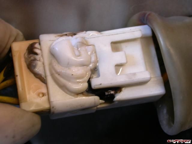
Totally melted white connector block - located on right hand side under fairing
Here is what you'll need:
- 12 Gauge wire (red and green - nice festive colors)
- 16 Gauge wire (black - goes with anything)
- 6 Gauge 1/4" lug (or any lug will fits on your battery terminal and is large enough to take 3 - 12 Ga wires and 1 - 16 Ga wire)
- 1/4" ring terminal (large enough to crimp in 2 - 12 Gauge wires)
- Connectors of your choice (female spade and Posi-Lock connectors shown - www.posi-products.com)
- 12 Gauge in-line fuse (this will be your replacement for the toasty 30 Amp fuse)
- Fuse block (not shown) - or 3 more in-line fuses
- Solder Gun
- Torch
- Solder
- Shrink Tube
- Tape
[image: gallery_11167_3051_105645.jpg]
Supplies
Here is the final result (note that I re-used my factory 30 amp fuse only because I screwed this mod up the first time):
[image: gallery_11167_3051_20211.jpg]
Finished product
How to:
First of all, I tried the "How To: Replace 30amp Fuse Wires, Charred 30amp fuse wires" post and succeed in mangling the positive post cable connector. There was absolutely no way I was getting that battery terminal de-soldered or pried off. In the end I ordered a new harness and just reused my old 30 Amp fuse holder.
*Leave everything on your factory battery harness as is. If you want you can repair the toasty 30 Amp wire and use that lead to power something but I'm not going to use it here.
Strip and twist together 3 - 12 Ga wires (red) and 1 - 16 Ga wire (black) - about 18 inches each or enough to reach wherever you place your fuse block.
[image: gallery_11167_3051_105684.jpg]
6 Ga 1/4 inch Lug and wires - ready to solder
Ready your 6 Ga lug with some solder cut and placed inside it. The first time I did this I used vice grips to hold the lug but I found that they soak up so much heat that it takes a while to get lug hot and the solder melted. The next time I did it I clamped the lug in between some wood - the lug heats up very quickly this way! Stand the lug up vertically so you can heat it with your torch and melt the solder - creating a pool of solder inside the lug. With the solder still liquid, jam the 4 wires that you grouped together into hot solder and hold the wires there until the solder cools. I suppose you could crimp the lug at this point but mine was a nice fit.
[image: gallery_11167_3051_85918.jpg]
6 Ga 1/4 inch Lug
Add some shrink tubing and your ready to test fit in the bike. I found there was more space around the back side of the battery - opposite the factory harness. 2 of the reds wires and the 1 black go to the fuse block. The other red wire gets an inline fuse and goes to the factory connector to the bike (where you disconnected the toasty section of the 30 Amp wire from - just seen in the top right side of the following picture).
[image: gallery_11167_3051_102666.jpg]
Battery Side - before tape
Next you'll need to remove your R/R. Kanadian Ken shows you how to do it here -- 6th Gen Monitor Wire Fix. I'll cover the monitor wire fix also.
Remove the 6 pin connector so that you can get at the 2 red charging wires and the 2 green ground wires (see Kens post on how to remove the spade connectors - a small jewelers screwdriver does the trick).
[image: gallery_11167_3051_143007.jpg]
R/R 6P connector removed
Here is the point of no return - where you modify the a factory piece - but hey it's only the R/R and that seems to need replacing on a regular basis anyway :rolleyes: .
Using 2 - 12 Ga (red wires - about 36 inches each) and 2 - 12 Ga (green wires - about 24 inches each) wires, I made "button hook" connections (covered on the forum somewhere?) to the charge and ground wires of the R/R.
To do that, you'll want to strip off about 3/4 inch of insulation from each of the factory R/R wires (the green and red ones). Then using my jewelers screwdriver, I opened up the factory wires in the center so that I could pass the new 12 gauge wire through. Once the new wire was through the hole I split the 12 gauge wire in two parts and twisted them tightly around the outside of the factory wire - closing the hole up. Then I soldered the connection and finished with tape. Finally, fit the spade connectors back into the 6P plug, but leave the black "monitor" wire out.
[image: gallery_11167_3051_6528.jpg]
Button hook connections
If I had to do it over again I would remove the factory black insulation jacket to about half way beween the 6P plug and the R/R and make my connection there. This would keep the mess of connections farther away from all the plugs and allow straighter wire runs. Just look at your R/R when it's on the bike and you'll see how much room is over the radiator - this would be a better place to make those connections.
Reattach the R/R and route your wires.
[image: gallery_11167_3051_69036.jpg]
Wire routing on right hand side
I initially made my connections to the R/R charge wires with Posi-Taps. However, they are quite large and there wasn't enough room for 4 of them. Another issue is that they come off at a 90 degree angle which is fine if it works for you. Lastly the posi-taps only make the connection with a small needle point and this seemed like a bit of a choke point to me. Here is a picture before I removed them, you can see the small hole they make ...
[image: gallery_11167_3051_93748.jpg]
FYI - Posi-Tap connectors - later removed
Instead I used the Posi-Lock straight connectors which make a nice solid, beefy connection - and they are removable (so I could pull the whole harness out to show you guys).
*You will also notice that the Black "sensing wire" was NOT put back into the 6P plug. It gets some shrink tube on it's rather long blade and then gets connected to a spade connector and run to the fuse block.
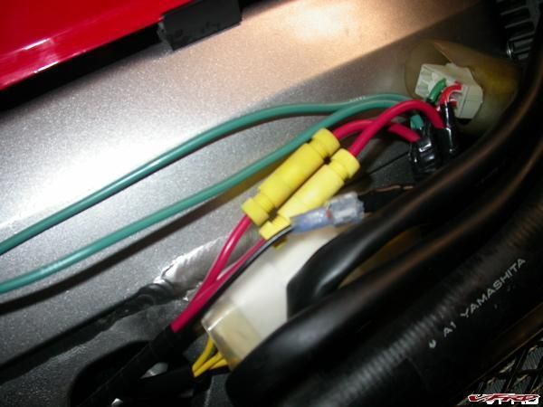
New charge and ground wires
Next, to attached the new ground wires, I crimped on a ring terminal and then added soldered for security. Since the grounds were a such a short run I didn't bother making a disconnect. I did wonder if I should run the grounds all the way back to the main frame ground (under the fuel tank) but after taking some resistance reading it would not have made a difference. The grounds hook up to the bolt that holds the fairing offset.
[image: gallery_11167_3051_108717.jpg]
New charge and ground wires taped
Then I measured and cut my wires from the battery and from the R/R to the fuse block. The fuse block is a nice little "Hella Splash Proof 4 Gang ATC Fuse Block, Spade Side Connectors HL62936". It was about $12 at the independent NAPA dealer here. Of course you could just use some inline fuses to do the job as well.
[image: gallery_11167_3051_13485.jpg]
Stolen Webpic of HL62936 Hella Splash Proof 4 Gang ATC Fuse Block, Spade Side
The one thing that I didn't like about the fuse block was that the base was open. I simply took some silicone and sealed it up - the top cover has a little gasket to keep water out. It's a pretty tight fit - I even used some pla-doh to check the clearance between the top of the fuse box and the seat - VERY tight.
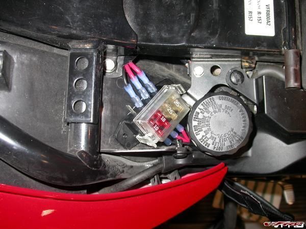
Fuse Block - close up
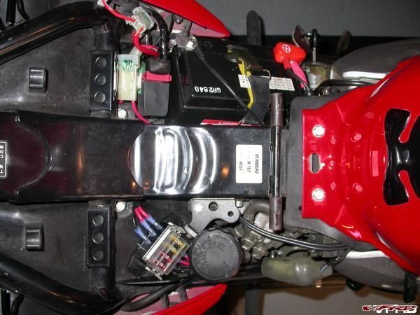
Fuse Block
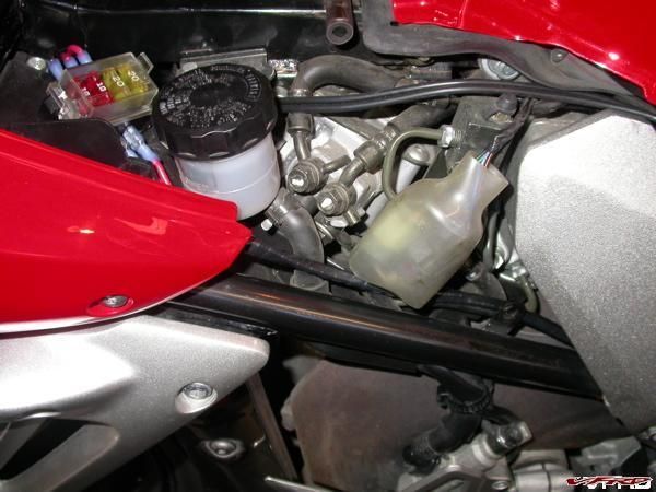
Fuse Block - side
With all the wires in place I then taped everything and zip-tied it into place. I also made sure to put dielectric grease on everything - new or old. If you want to reverse this mod (lets say for warranty reasons) you'll need to cut the wires from the R/R or buy a new R/R and then simply remove the harness.
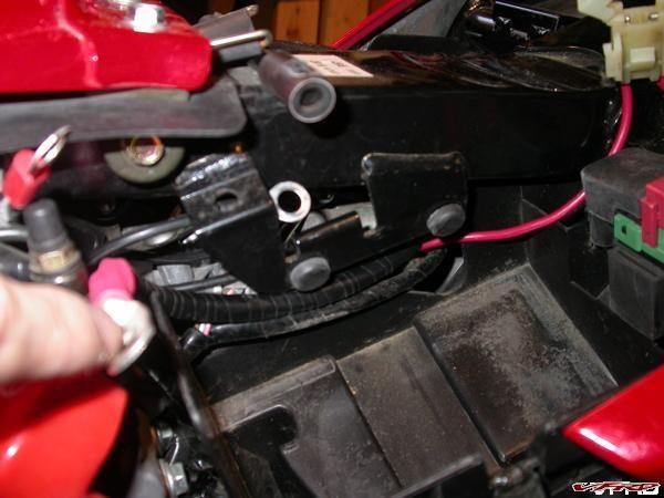
Battery Side - routed behind battery
[image: gallery_11167_3051_101454.jpg]
Taped and routed
In the end my beefed up charging system now has three routes - 1 factory routing and 2 re-enforced routings direct from the R/R. The grounds from the R/R are beefed up and redundant which should hopefully help. And finally, running the the black monitor wire directly to the battery solves any issues with resistance in the ignition circuit causing overcharging.
I haven't quite decided on what size fuses to use in the charging wires - I started with 25 amp then switched to 20 Amp fuses.
[image: gallery_11167_3051_28948.jpg]
Stock RR and Suggested Rewired RR
My charging voltage is stable at 13.4 to 13.5 (edit - must have been drinking when I wrote that) 14.3 to 14.5 volts with high or low beams on, from idle all the way up and I am much more confidant with the electrics now.
The last thing I added was a voltmeter to monitor the situation. You can see it here at Lascar Voltmeter Install Pics.