VFRDiscussion ARCHIVE / READ-ONLYREAD-ONLY

Cam reinstall - timing help needed

66 posts Started 9 Aug 2017 Last recovered post 1 Mar 2019 Wayback Machine snapshot 20 Sep 2019

#1

Need some help with my '98 5th gen can reinstall. 

I've done the clearances but made one big boo boo: took the cams out of BOTH front and rear cylinders so don't have a reference for reinstallation. 

In my defence the Haynes manual did not explain that only one side of the engine should be done at a time (or perhaps I missed it). 

Do I just turn the crank over to the right symbol and install one of the cams, then install the second one in reference to the first one? Or is there some other mark on the flywheel (or someplace else) that I need to alight the cams to? 

Does it matter where the cams get installed on the cogs if they are aligned properly to each other (and markings in the crank)? 

What confuses me is that with the correct mark showing in crank, sometimes the lobes are aligned correctly and sometimes you need to cycle the engine round one more time. So the mark is only correct 50% of the time. How do I know if I'm on the right or wrong cycle of the mark? 

How do mechanics reinstall the cams after a rebuild? 

I'd appreciate any advice you can offer. 

Thanks, 

Stray 

#2

The cams are mark FI FE & RI RR   (IIRC) for front intake, front exhaust, rear intake, rear exhaust  its cast into the body of the cam between the bearing faces.

For the timing, use the manual its available to download here. The front & rear banks have their own timing, it onlyt matters that the correct piston is at TDC when you install the cams. Use a soft rod like a wood dowl down the spark plug hole of the required.

Have fun.

#3

Drawing on 4th gen experience here, but pay attention to when they say timing arrows or timing marks. There are 2 distinct types of marks and are used for different alignments.

#4

Not to stray off topic but how many miles on your bike and which valves were out of spec and by how much? I am on my second 5th gen. Last one needed no adjustment until well over 100k miles.

#5
2 hours ago, Mohawk

Use a soft rod like a wood dowl down the spark plug hole of the required.

Have fun.

Dowel down the plug hole - that's genius! This answer really cheered me up. Big thank you Mohawk. 

2 hours ago, auggius

Drawing on 4th gen experience here, but pay attention to when they say timing arrows or timing marks. There are 2 distinct types of marks and are used for different alignments.

Thanks for this auggius - will keep an eye out. 

#6
1 hour ago, VFR Capt.Bob

Not to stray off topic but how many miles on your bike and which valves were out of spec and by how much? I am on my second 5th gen. Last one needed no adjustment until well over 100k miles.

My 5th gen has 60k miles in it and every single intake needed adjustment. Two of them were particularly bad. 

Hand drawn measurements attached. Sorry for the untidy pics. 

The intake ports arts are all in the middle (outside exhaust valves were spot on).

The big number is feeler gauge read. The F: figure is shim size printed on "face". Most don't have a number because they were so worn the figure had been rubbed off. The Mic: figure is shim size measured by "Micrometer". 

Particularly tight tolerances in cylinders 2 and 3. 

Stray

[image: IMG_4283.JPG]

#7
5 hours ago, Stray

Need some help with my '98 5th gen can reinstall. 

I've done the clearances but made one big boo boo: took the cams out of BOTH front and rear cylinders so don't have a reference for reinstallation. 

In my defence the Haynes manual did not explain that only one side of the engine should be done at a time (or perhaps I missed it). 

Do I just turn the crank over to the right symbol and install one of the cams, then install the second one in reference to the first one? Or is there some other mark on the flywheel (or someplace else) that I need to alight the cams to? 

Does it matter where the cams get installed on the cogs if they are aligned properly to each other (and markings in the crank)? 

What confuses me is that with the correct mark showing in crank, sometimes the lobes are aligned correctly and sometimes you need to cycle the engine round one more time. So the mark is only correct 50% of the time. How do I know if I'm on the right or wrong cycle of the mark? 

How do mechanics reinstall the cams after a rebuild? 

I'd appreciate any advice you can offer. 

Thanks, 

Stray 

Like people have already said, it's no big deal to re-establish the timing after removing both the camshafts from both the front and rear heads.  When you are careful and read the manual before-hand it is logical and straight forward...

Step #1.  Do as you have been told and download the manual.

Step #2.  Read through (carefully) the section that describes the procedure for re-establishing the timing.  Read it as many times as necessary for it to make perfect sense.

Step #3  As per the manual: re-establish the timing on the rear head.

Step #4  As per the manual: re-establish the timing on the front head.

Step #5  Pat yourself on the back for being such a good motorcycle mechanic.

#8

I'm not sure what causes tolerances to change. Is it spot or carbon build up? Could it be caused by hot running, poor fuel or wrong oil? What about short journeys in traffic vs long journeys on highway? 

Im not an expert but expect every bike will be different because they all endure different conditions. 

Clearly my my bike has led a different life from Capt.Bob's. 

On on the other hand perhaps your dealer couldn't be bothered with this awkward job and just told you everything was fine? Of course you may have checked tolerances yourself and found them within spec - I don't know. 

YMMV

#9
15 minutes ago, Stray

I'm not sure what causes tolerances to change. Is it spot or carbon build up? Could it be caused by hot running, poor fuel or wrong oil? What about short journeys in traffic vs long journeys on highway? 

Im not an expert but expect every bike will be different because they all endure different conditions. 

Clearly my my bike has led a different life from Capt.Bob's. 

On on the other hand perhaps your dealer couldn't be bothered with this awkward job and just told you everything was fine? Of course you may have checked tolerances yourself and found them within spec - I don't know. 

YMMV

I've wondered about this too...

Just like your post above, my exhaust valves were perfectly within spec (and I mean perfect, like the bike had just left the Honda factory), but on the other hand, almost every one of the intake valves were out-of-spec toward the too tight side  (just like your bike).  And this was on a bike that only had 19,000 miles on it.  

If the tolerance change was due to carbon build-up (on the back side of the valves or on the faces of the valve seats in the cylinder head) wouldn't they go out-of-spec toward the too loose side as the gap at the top of the valve stem was made wider by the carbon build-up?  So it has to be something that would induce a change that decreases the gap from the original factory-set specification.  Are the intake valves changing shape?  Are the valve stems stretching?  Or are the intake valves becoming more deeply seated into the cylinder head, meaning: are the valve seats becoming slightly deeper, is the aluminum structure becoming compacted?  Or are the valve faces beginning to "tulip" a bit?

I know that exhaust valves are normally build a bit more robust than intake valves because they have to deal with higher temperatures.  So maybe that explains the difference.

#10
11 minutes ago, GreginDenver

Step #5  Pat yourself on the back for being such a good motorcycle mechanic.

GreginDenver, thanks for your advice (and Mohawk and auggius). I will follow it. 

As for back patting, I am just your run-of-the mill home mechanic trying to keep his machines in good order despite work and family pressures. Not quite what I'd call a "good mechanic" but happy to have a crack at it. 

Also, like many others on this site, I get some pleasure out of it. 

Have rebuilt quite a few a few bikes using Haynes manuals but the VFR manual is not up to the same high standard as the others. Looks like the Workshop Manual available here is the way forward. 

#11
9 minutes ago, GreginDenver

I know that exhaust valves are normally build a bit more robust than intake valves because they have to deal with higher temperatures.  So maybe that explains the difference.

GreginDenver, if you're right about the exhaust valves being tougher then it probably has nothing to do with the aluminium head and everything to do with the valves themselves. After all, both In and Ex valves slap the head with the same speed/force - they are turned by the same mechanism. Why would only the In valves be suffering? 

In my my uneducated mind the Ex valves should be suffering most as the hot gasses, soot  and contaminants flowing through them are much worse than the clean fuel + air flowing through the In valves. Just goes to show how little I know. 

Does this his mean we can replace the intake valves with tougher exhaust valves and enjoy longer valve clearance service intervals? 

This is is just a lay stab-in-the-dark. I'm not a professional. 

Stray

#12

Interesting question here...

My understanding is that clearances decrease with time as the valve wears into the head. So maybe the carbon build up on the exhaust valve cushions them a little and preserves the clearance better than the clean valves on the intake? My experience on my three bikes (5G VFR, VTR1000 and ST1100, which all use the same cam/bucket/shim arrangement) is the same, intakes are the valves more likely to close up.

I do know that the exhaust clearance needs to be greater than the intake to allow for the greater thermal expansion of the hotter exhaust valve.

And to answer one of the original questions about crank and cam timing; always remember that on the four stroke, there are two crank revolutions per power stroke. That is why the cams run at half speed compared to the crank, so that each cam goes through a single revolution per power stroke. The piston is at TDC twice per power cycle, once with the valves open at the end of the exhaust cycle, and once with the valves closed at the top of the compression cycle. As the ignition fires at every crank revolution (the ignition pulse generator is off the crank) it does not matter whether you start the cam timing exercise on a "compression" or "exhaust cycle" but it is very important to get the four cams into the correct relationship to each other. As stated, read the service manual carefully and don't deviate from the procedure.

I know from the VTR1000 forum that it is possible to time the both cylinders correctly, or with one cylinder 360 crank degrees out of position; all the timing marks line up fine and the bike starts and runs OK but apparently loses its ability to run at high revs, which i would expect has something to do with intake or exhaust resonance. 

Because I doubt my own ability to get these things corrected easily, I only ever work on one cam at a time on my bikes. On my VTR (chain driven cams) I pull the cam off the sprocket, and leave the sprocket cable-tied to the chain so I can't lose timing.  This is a great idea until you refit the cam, and turn the crank without remembering to cut off the cable tie first....

#13

Pretty much agree with what has been said, deffo read the manual, especially section 8-28

If all cams have been removed pay particular attention to the rotation of the crank between rear and front installation.

450 degrees (1 and 1/4 turn) and ensure no. 4 cylinder is at TDC. Section 8-30

#14
Terry, 09/08/2017 at 10:38 PM

And to answer one of the original questions about crank and cam timing; always remember that on the four stroke, there are two crank revolutions per power stroke. That is why the cams run at half speed compared to the crank, so that each cam goes through a single revolution per power stroke. The piston is at TDC twice per power cycle, once with the valves open at the end of the exhaust cycle, and once with the valves closed at the top of the compression cycle. As the ignition fires at every crank revolution (the ignition pulse generator is off the crank) it does not matter whether you start the cam timing exercise on a "compression" or "exhaust cycle" but it is very important to get the four cams into the correct relationship to each other. 

Terry, you've hit the bullseye!

If the ignition fires at every revolution of the cams then I just have to ensure piston is at TDC and  crank/cam markings line up as specified. Then I just have to ensure the second cam is installed in correct relation to the first. 

Thanks for the advice everyone. I've now read the Workshop manual which says to turn the crank until the correct mark lines up and "ensure piston is at Top Dead Centre". It doesn't explain how to check if piston is at TDC so Mohawk's dowel-down-the-spark-plug-hole suggestion is gold. Thanks again Mohawk. 

Finally does everyone replace the o-rings under the cam cover when they do a valve job or just reuse the old? Dealer wants silly money so I'd rather not buy if unnecessary. 

Thanks for your help - really appreciate it. 

Stray 

#15

No I have never replaced the o-rings on the cam cover. Just make sure you put some sealant on the half moons on the main gasket, the flat parts don't need it but the moons will weep without sealant. Don't over-tighten the cam cover bolts, have heard plenty of horror stories about snapping off the mounts in the head. 

#16

With your question about replacing rubber parts you've stumbled into one of the weirder areas of VFR800 myth and legend.  You may have already noticed that VFR owners are quick to crow about the longevity/durability of the engine (and maybe even the whole motorcycle too).

This "VFRs last forever" thing goes to different degrees with different people, some take it to extremes, like, "My VFR has 100,000 miles on it with nothing but gas, oil changes and air in the tires!"  The unwillingness to replace even normal consumables like rubber gaskets becomes a point of pride.

#17

I've replaced plenty of rubber parts on my 99, all the radiator hoses for example. But I've never noticed any weeping from the cam cover o-rings.


Sent from my iPhone using Tapatalk

#18

Thanks GregDenver and Terry. I'll follow your advice about o-rings and sealant. 

Every bike manual I've had says to replace just about everything you unbolt. If they had it their way you'd be rebuilding a brand new motorcycle every 5,000 miles. 

On the other hand I do like to replace "consumables" and keep on top of maintenance. Yes, a bike can run for ages on the original parts but a refresh can really enhance the joy of ownership. Changing wheel and swing arm bearings can make a tired old machine feel like new. Same with new spark plugs, filters and oil. 

But when o-rings cost more than premium bearings I feel a bit aggrieved and somewhat disobliging toward Mr Honda. 

#19
1 hour ago, Stray

Thanks GregDenver and Terry. I'll follow your advice about o-rings and sealant. 

Every bike manual I've had says to replace just about everything you unbolt. If they had it their way you'd be rebuilding a brand new motorcycle every 5,000 miles. 

On the other hand I do like to replace "consumables" and keep on top of maintenance. Yes, a bike can run for ages on the original parts but a refresh can really enhance the joy of ownership. Changing wheel and swing arm bearings can make a tired old machine feel like new. Same with new spark plugs, filters and oil. 

But when o-rings cost more than premium bearings I feel a bit aggrieved and somewhat disobliging toward Mr Honda. 

Actually I'm kinda new to VFR ownership.  I always admired the VFRs, especially the models with the gear-driven cams, but I was busy with life and work and by the time I got around to buying one (just this past December) the bike was 18+ years old.  

So I didn't hold back on the effort when it came to refurbishing it.  Now that I finally had a VFR I wanted to feel what the VFR800 felt like when it was new (what I missed out on back in 1999).

What I'm saying is: there are a lot of rubber gaskets and O-rings and such that have never been replaced on a lot of these 5th Generation VFRs.  And here we are, buying these 19 (going on 20) year old bikes and some of us want to act like they don't need a deeper level of care.

Here's what I did to my 5th Gen after I purchased it this past Devember: http://vfrworld.com/threads/refurbishing-my-99-5th-gen.52488/

#20

Neat write up on your rebuild. One thing I'd say, is that after that amount of strip down, cleaning & replacement. You didn't do the head bearings !? Which is a known area where the factory skimps on the grease, so even if you didn't replace the OEM bearings, they still have 20 year own hard grease in there !

#21
5 hours ago, Mohawk

Neat write up on your rebuild. One thing I'd say, is that after that amount of strip down, cleaning & replacement. You didn't do the head bearings !? Which is a known area where the factory skimps on the grease, so even if you didn't replace the OEM bearings, they still have 20 year own hard grease in there !

You're exactly right about the head bearings, my winter efforts ended short of a complete end-to-end refurbishment.  I ran out of time and that was the item that I decided to skip.  I've got another (much smaller) maintenance session tentatively scheduled for this fall.

#22

Wow Greg, that was one mother of a thread. Bike is virtually brand new now and I'd bet she runs beautifully. 

Difference between your refresh and mine is mileage. Yours had lowish miles and was cared for whereas mine has 65k on it and has clearly seen a lot of winter salt/abuse.  

As as such I'd be wasting my efforts and money going your route as my bike doesn't deserve it as much as yours. In England we say, "you can't polish a 7urd but you can roll it in glitter".

Of course I'll make her safe and refresh whatever I can but it will all be done on the cheap - can't justify throwing real money/time at her. 

So so far all I've spent is service parts (plugs/filters/oil), brake fuid, coolant, shims (Mr Honda screwed me on those) and tyres.  And a big dollop of elbow grease, of course. 

Still to come are bearings all round, seals and fork oil. 

Might throw in a few mods like PAIR plates, rear shock and possibly an USD front end off eBay (all as cheap as possible).

None of that will bring my bike anywhere near your high standards but it will run well and I will enjoy it. 

Your refurb is by far the gold standard - really well done. As a VFR owner I'm really grateful for the effort you put into that and am inspired to emulate (albeit at a lesser extent). I really hope you get maximum joy out of your lovely bike for many years to come. 

Stray

#23

Thanks for the help everyone. With the Manual and your advice I got it all buttoned up. 

A few notes for anyone doing this themselves: 

1. It is very hard to judge the if the timing marks are set flush if the engine is still in the bike. There's just not enough room even for a tiny mechanic's mirror. My solution was to use a popsicle stick along the top of the engine and contort myself to see if the marks line up correctly. 

[image: IMG_4344.thumb.JPG.3973d574bd9a23ea38b65d6039ee9bc0.JPG]

2. With the piston at TDC and timing marks facing outwards (as per manual) the cam lobes are partially engaged on one cylinder. I noticed this especially with the exhaust lobes on cylinder 2. Buttoning up the cam holders with valves slightly engaged forces the cam into its bearing races but the pressure is bad for the holder and could warp or break it. It also forces the crank over slightly messing up your alignment marks. The way arround this is to set the timing marks as instructed loosely and then rotate the engine SLIGHTLY off the mark so the valves are not engaged, before bolting the cam holder down.

When you button it up it will look wonky until you turn the crank back to its marking again - now your cam markings will lign up correctly. 

This is the crack turned slightly off its TDC

[image: IMG_4360.thumb.JPG.93243121d0889924b210098ce140c6f8.JPG]

This is how the markings looked after bolting up - slightly off. Red marks made by me on disassembly. 

[image: IMG_4342.thumb.JPG.2c010c24c6af3a0c1582e829d28ef73c.JPG]

When the crank is returned to TDC the markings line up perfectly (no pics, sorry). 

Truly a laborious process that took over 5 hours, most of it head scratching. 

Havent yet rechecked valve clearances in case in case one of them is out and I need to redo this. Can't face it just now.

 Stray

#24
3 hours ago, Rush2112

Quick observation on your R/R replacement.  R/R use the subframe as a heat sink to help dissipate heat so they need to mount with the back of the R/R flush against the mounting plate to facilitate heat transfer. It may not be an issue since the one you are using is so oversized and may have enough cooling with the fins surface area but it is something to look out for especially on long tours.  If the R/R gets too hot turn on your high beam headlights to help reduce the shunt load on the R/R.

He's using an OEM series-type reg/rec, so in theory there won't be massive amounts of heat to dissipate in the first place!

Ciao,

#25
18 hours ago, Rush2112

I just read this thread and I think it is awesome how you are giving your VFR a new life.  Good luck on the reconditioning!

There were a couple of questions throughout the thread that I may be able to provide some insights:

Regarding valve clearances, the valves usually tighten up from recession into the valve seats from millions of impacts. Older metallurgy allowed valves to stretch which also led to valve tightening but modern valves generally don’t suffer from this as much as in the past.

Regarding the force of valve impacts, intake and exhaust impacts are not necessarily the same. The speed of the valve is dictated by the cam profile, the duration and lift of exhaust and intake cams are often different so the valve closing speeds can be different; in our 5th gen engines cam lift and duration are the same (8mm and 225 degrees) for intake and exhaust so this simplifies things. The valve materials are different so they have different densities and they are different sizes; therefore, the intake (29mm) and exhaust (24.5mm) valves have different mass so they have different momentum when impacting the valve seats. This is likely why you see a difference in intake and exhaust valve clearances.

Quick observation on your R/R replacement.  R/R use the subframe as a heat sink to help dissipate heat so they need to mount with the back of the R/R flush against the mounting plate to facilitate heat transfer. It may not be an issue since the one you are using is so oversized and may have enough cooling with the fins surface area but it is something to look out for especially on long tours.  If the R/R gets too hot turn on your high beam headlights to help reduce the shunt load on the R/R.

sorry for the zombie resurrection of previous topics... they were new to me tonight  :goofy:

Thanks for the advice, Rush. I’m flattered you read my thread and grateful for the advice! Your posts on this thread have been a great source of information and inspiration. 

JZH, you’re probably right about he overkill RR being able to cope (it barely even gets warm) but it didn’t hurt to use a good heat sink. 

This new type or RR not only has huge capacity to absorb over-current, it also controls how much is put out in the first place. At least that’s what the Triumph site I read said. So it doesn’t need to work as hard and doesn’t get as hot. 

Stray

#26

Removed subframe this afternoon - wiring harness and ECU was holding it in. 

Now to fit CBR600 F4 alloy subframe instead. Curiously, the 5th gen subframe is shorter and sexier than the CBR, which is a dedicated race bike? 

[image: 2BA79820-3190-429E-98C0-33A08C33FFC7.thumb.jpeg.56418a01dcf8b09ec1012371661b0c8e.jpeg]

Also, the 5th gen subframe has a sexier upward sweep than the CBR, again not what I was expecting (seat fits on the left edge in pic below). 

[image: D483225D-A2C4-4B81-A2E3-4AF4931E9D17.thumb.jpeg.501f0c9d9097f3c18067c72bd2da4ecb.jpeg]

Showing roughly where the CBR subframe will need to be cut to match up 5th gen mounting points. Works out quite well! Mounting points are about 5mm too narrow on 5th gen frame so spacers/washers will be required. 

Another shot side-by-side. 

[image: 4B65525D-ED53-4570-A295-6B503E860585.thumb.jpeg.0dba01bbf6973d747dc520e2dcf76b80.jpeg]

From above you can see both subframes are virtually identical in width. I suppose a rider’s @rse is a rider’s @rse is a rider’s @rse whatever he rides...

[image: AAC00B5B-ACB0-48FE-A72E-8B34BAD8F1EE.thumb.jpeg.bc2796bc36273aeaf8a4a956ae3f0696.jpeg]

Few shots showing the Triumph 675 tail section I plan to fit instead of the stock unit. Hard to line things up properly but gives an idea. The seat units are placed side-by-side with the bump stops lined up. I’m hoping to keep the stock seat as it matches the tank grooves but will need cutting down to a mono unit. 

[image: 28F758ED-ABCC-49A0-8FD9-F5D5B8FD17BC.thumb.jpeg.745601e1e5aa55d3e176f6db71d8ce03.jpeg][image: 87122359-EFC9-41B5-ADF4-35FACD4CFB9B.thumb.jpeg.33012c6025a20a51c492d338300acbca.jpeg][image: 50F66CD3-FE65-446D-8777-D5FA2BAD3E62.thumb.jpeg.111077ef9a2fa445eb852ec9dbd158cb.jpeg][image: AEC09684-A253-4FB2-B59D-2FFAC8D2E244.thumb.jpeg.fa65d280f7a3fcd1c9e1c510c6df8e6d.jpeg]

As things stand the tail section should be a hair longer than the end of the stock duo seat. In effect the pillion seat will be cut off to make room for the new Triumph 675 tail fairing. 

Was as going to hack at the CBR subframe today but lost my nerve and ran out of time. Need to take a few measurements and pull my finger out. 

Ideally I hope to get the tail section running parallel with the tank. Will require a bit of trial-and-error hacksaw work! 

Stray

[image: 23D260EE-8117-4798-9E7E-E5603D36CE52.jpeg]

#27

Spent about 45 minutes trying to remove the sprocket side rear nut and the only thing I achieved was to bend the breaker bar! 

By the way a good method to loosen the nut if you don’t have brakes or a spare pair of hands is: push a wooden shovel handle through the rear wheel and wedge it against the swingarm (chain guard removed to save it breaking), then position the bar at 9-10 o’clock so you can stomp it down. This keeps the forces aimed downward and less likely that you’ll push the bike forward off its stand. [image: B7A6599E-B68A-4803-812B-AFD46DA52258.thumb.jpeg.68d92872278a629316552fd785f56f84.jpeg][image: 11B98828-D2EE-4431-B90B-AB855B8FDAB8.thumb.jpeg.f9d7b9e6de3a011d29ba99dd53ae65ae.jpeg]

Thought I was being clever here but I still failed to loosen the nut.

You can see where the bar has bent. I’ve used this old steel shelving tube for many years on various motorcycles up to 150 ft pounds of torque. Today is the first time it let me down! 

So I pulled out the torch and applied some heat/lube then hit it again... and bent the other side of the bar! 

So I applied a bit more heat/lube and reached (to my shame) for the last resort of any exasperated home mechanic - the 4LB sledgehammer...still no joy! 

I gave up and wheeled the bike into the shed for another day. Whilst doing so I realised the huge pressure applied to the nut had dug the sidestand 1.5 inches into the tarmac! This is the unexpected drawback of my “clever” method outlined above. And the fact it failed to loosen that blasted nut...

Stray

#28

An air or electric rattle gun would be the tool for this job. I had a similar issue, and my local bike shop used their rattle gun and the nut came off easily after a couple of seconds. I now own  a gun of my own, and it has been a great investment.

#29
1 hour ago, Terry

An air or electric rattle gun would be the tool for this job. I had a similar issue, and my local bike shop used their rattle gun and the nut came off easily after a couple of seconds. I now own  a gun of my own, and it has been a great investment.

Thanks Terry.

Question is what do I do now the bike is in pieces and I have no access to a rattle gun? 

More heat and lube i suppose...

#30

Can you hire a rattle gun? I have an electric one, mains powered, cost me less than GBP50 at a local hardware chain store. 

#31

No, get a longer lever!  A scafold pole is the old standby. 

I had an eBay swing arm I wanted to dis-assemble, but no bike to mount it on, so this was what I did:

[image: 836119066_2016-03-2514_06_07x.thumb.jpg.c09c73b4f15bb4af10be81c73b91122b.jpg]

I didn't have a socket handy, so I used my trusty 24" Craftsman C-wrench (it's fine if you're careful--and lucky!)  I used a square steel tube (about 2"x2") to keep the axle from turning.  The nut loosened without any drama, IIRC.

(You did un-stake the nut, right?)

Ciao,

#32
10 hours ago, JZH

(You did un-stake the nut, right?)

That's what I was about to say.

Plus the tube you are using doesn't look very strong.

#33

Thanks for the advice guys - I mean it. 

Terry, I’m not sure you can hire a rattle gun in the UK? Not that I know of anyway. I could just pull the swingarm and take it to the local garage as a last resort. 

JZH, very clever what you did to that loose swingarm. And yes, I did unstake the nut. I REALLY unstaked it with a big @ss chisel and may have ruined it. 

VFROZ, you’re right about that bar being a bit weak but it’s a solid steel bar. Took all my weight jumping on it to bend like that. 

Scaffold tube is definitely stronger so I might grab one when family obligations allow. 

Thanks gents. 

Stray

#34

Stray - another trick I did quite a while back is - I had a left over 8 foot long oak plank in the garage and I drilled the wheel bolt pattern into it.. then bolt on the plank to the lug studs with lug bolts.

Instant monster torque arm.  Also use for re install the 36mm bolt. - Oh yeah... used a 3/4" breaker bar to get that thing off... 

I think if you get the bike on the center stand, it would work better. 

[image: image.png.e2f272e4dbe294100ad0e9eab146432e.png]

#35

Thanks Mello, I was very impressed by that idea! Saw it in another thread. 

#36

Progress is painstakingly low but I had a brief crack at the alloy subframe conversion for my Triumph 675 tail conversion. 

First, a weight comparison of the stock subframe vs the alloy CBR600 F4. You’ll note there’s not much in it, which I found disappointing. Used an old fishing scale so might not be spot-on but gives a good guide. 

Here’s the F4 at just over 3.5kg:

[image: 3221AC7B-8340-4DDD-9B5E-E6A3A9C5BAEC.thumb.jpeg.a0eb44350b87561e058109d379c71ddb.jpeg]

[image: 7329A749-88D9-4C78-9462-515AAE574A96.jpeg]

Here’s the 5th gen at about the same: [image: 3DABA7B1-0D6D-4595-B96B-B98DC2EEA9A2.thumb.jpeg.3addeed6d7c6468d14430c2ea0e6567f.jpeg]

[image: 69BB74A9-CE8D-42F7-8DCF-292567B9C82F.thumb.jpeg.7869b7e41bd7cd7de822bb8b021f2111.jpeg]

I was really disheartened by this, thinking it isn’t worth the effort (all the fabricating I’d have to do plus issues with the undertray etc), but the CBR sub is quite a bit longer than the VFR so I thought maybe I’ll cut off all the extra bits and weigh it again. 

Here’s the measurements written down in case someone wants to do this later but NOTE: the short bolt spacing marker is wrong. It should read 1.5cm, not 1cm

[image: 76D35D9C-992F-4D98-8D73-23AA71129D12.thumb.jpeg.8af8079b7b81bc3014d847d64f98d3e8.jpeg]

[image: 5204AF35-AC33-4392-B45F-020802BDB8EC.thumb.jpeg.fed9c89c51c15d00d4b12defcd998027.jpeg]

After cutting off those bits (there were some hefty mounts for the seat catch) this is the weight: 

[image: 13968DE4-A254-4209-832C-5BF946F1A05F.thumb.jpeg.516cd5771f8a5741d229f1a203dbc42b.jpeg]

That’s just under 3kg, 1/2KG saving with a bit more to cut off. Also, the seat catch on the F4 is HUGE and heavy as made of steel plate (rest of the sub is alloy). 

Here’s the seat catch on its own: 

[image: 98D79DF4-4879-47A3-9F22-C5C79C59EC56.thumb.jpeg.06c81d16a3f3b63267e1ec4612aaaa01.jpeg]

At one point I got tired of hacksawing all the little tabs that needed removing so I just pulled them off with a big pair of pliers. Was surprised how easy they peeled off! 

This is is what the frame looks like now: [image: 1F39AA80-A64C-4887-8AB4-328C3A2A0EAC.thumb.jpeg.01b62078546e9a3ff58ff14ca2e3c40c.jpeg]

But the Triumph tail still won’t quite fit: 

[image: 11E0F751-364B-40FB-873D-0F7949346C73.thumb.jpeg.52df1bbd6779b9db208232a13c25db97.jpeg][image: DBDF1F31-CC73-4102-BF64-D12547099537.thumb.jpeg.922126945218f56f5357b7861a6fc9ba.jpeg]

The sub bits sticking out above will need to be bent towards each other so they can fit in the triangular rear fairing. Not quite sure how I’m going to achieve that but I imagine a blowtorch will feature I’m my future...

If I’m lucky this cut will make it fit but I don’t like the loss of strength it will mean (bottom of square section will be lost) but then again that bit will only carry the plastics and light as it is a single-seater now. 

[image: B5EB701F-85A3-40C7-A5EB-E7624D3D8B5B.thumb.jpeg.a342f9aef236ba8f0ad8300501dba860.jpeg]

Stray

#37

I read a good part of this thread tonight and I think that you are getting right into the resto. Good on you.

I,ve just done a front end and full rear axel and swing arm service on a 2000 Gen 5 that I've owned for 2 months and plan on taking up to Cairns soon. Lucky for me my axel nut came off eazy with a rattle gun. The wheel nuts however were bastards... my breaker bar looks like a coat hanger!

If your bike were mine, I'd have the swing arm off it and laying tire side down while I juiced the nut and thread with the most potent penetrating oil I could get on it for about a week. Then use a rattle gun. Under that nut, you also have a spring washer, collar, cush drive bearing, collar and cush drive flange splines to come off yet. With luck you will have an eazier time getting them free than the nut. Lots of penetrating oil...

The nut on the inboard end of the suspension linkage was also a bastard on my bike, I had trouble with the spanner rolling off the nut. Wedged it on in the end.

I found that nearly all the dust seals on the suspension and rear axel were on their last legs and the double ball bearing in the bearing hub has been spining on the axel $$. The grease in all the bearings needed cleaning and replacing.

You might find success cleaning the non painted aluminium surfaces with oil based degreaser and very fine steel wool. On painted surfaces it rubs through the paint, don't use it.

You shouldn't need too much strength on the very end of your sub frame. Holds a couple of lights, wires and bits of platic!? I don't think chopping it on those marks will hurt. Maybe epoxy in a wedge of hard plasic between the two square sections ahead of the weld and extend it beyond where you cut the back out of the lower square section? Helping support the upper rail where you havn't weakend the lower one.

Hope this info helps.

Cheers

Z

#38

Thanks Zarquon, both for your advice and for reading this far! 

Havent had a chance to tackle that rear nut again but will  be soaking it with penetrant as you suggest. Plan is to loosen ALL nuts on wheel/suspension while bike is together and wheel can be used as a chock.

Most guys here have struggled with loose swingarms and wheels as it’s harder to get good purchase. If oil and heat don’t do it I’ll use your “on it’s side” advice as a last resort. 

Thanks for your subframe advice too - will be going that route! 

Congratulations on getting your resto done so fast. I’ve owned the bike for two years and not got as far as you have - respect! 

Stray

#39

Just in case you didn't already know what was behind that nut. The second pic is in order of the way it came off.

It all went back together today and is sitting pretty on a spanking new T30 EVO GT and no slop in the linkages any more.

[image: 20180731_112756.jpg]

[image: 20180731_112747.jpg]

#40

After lots of life happening I finally got a chance to have another go at removing the rear hub...with a little help from my scaffolder friend! 

Did somebody say BREAKER bar? Note the wooden shovel stuffed through the front wheel spokes. 

[image: 65070985-6951-4F9A-928C-AA53AF431595.thumb.jpeg.a749e81ce74c6ebace509c3ac4ea28b9.jpeg]

Well, that rear nut was so seized my entire weight on the scaffold tube wouldn’t shift it! Half inch socket handle was bending like a banana - thought it was going to snap. 

So out comes Mr Mapp Gas Torch to play with Mr Scaffold Tube and this time they got it loose between them. Soaking with penetrating oil overnight might also have helped. 

[image: 3828CC39-CF8D-4B3B-97B4-0DF6A0E197C8.thumb.jpeg.d66a5bb2b8d0415a2b45bb9913ca024c.jpeg]

Got the sprocket and cush drive off easy enough but the rear calliper took a bit of figuring out. 

[image: 391FDF53-4197-4CB1-B8F5-30BB61FF6BDD.thumb.jpeg.7aea99d9bff6d3560587db0810e783cf.jpeg]

Stripped it almost all off but ran out of time and couldn’t tackle the giant circlip to get the last bit done. Very frustrating when there are time limits on wrenching. 

[image: 579D457F-9F46-4703-B54F-EB01E6D6C80D.thumb.jpeg.a6046a0a7c84ecf393f745d25268771a.jpeg]

Had to bolt it all back together loosely to put bike away and go to work. That means taking it all apart AGAIN next week when I get another 1.5 hours to wrench.

At this rate my children will inherit this unfinished project in 20 years time...

#41

Nice going... getting that b@$tard undone... progress!

#42

It looks like it was a real battle!  Glad you won!

Ciao,

JZH

#43

[image: 1C5DE1A2-F8D9-47C4-9F3C-2BF259FE6EC5.thumb.jpeg.449f83d0b4f9517ec1a4a2d69d3ee895.jpeg]Rear wheel now on! 

#44

Last week I took the plunge and removed the throttle bodies. Was worried about rubber boots being too hard and brittle after 20 years and 70k miles. 

Anyways, had to buy an extra long extension thingie to reach the rubber boot clamps. Despite some pretty serious corrosion they came undone without stripping (got to push against the screw pretty hard).

Ordinarily there’s no place for crowbars in motorcycle wrenching but some gentle application against the rim (working slowly along with some protection for rear cylinder head) popped rear boots right off. A little wiggle and the front boots also gave way. 

[image: 8C8C7ED9-78EE-4B88-8BC1-57EA02B61860.thumb.jpeg.8a9badbd8faff8ad87dd382f493404c3.jpeg]

Here they are in all their filth and rust. 

[image: 539EE2C9-2633-46A0-99A0-B4B892FCA07F.thumb.jpeg.c83b22cde9e697d43c366f1bfc2d29d6.jpeg]

Note the cardboard box is from a Vtech Christmas toy - I thought that was funny! 

[image: 9F9B3F3C-A2E0-44B8-A6F6-87AE14419147.thumb.jpeg.9c388cdf7fea65f2245e0e06a1125b21.jpeg]

Closeup of the butterflies shows some black buildup on the opening edge. 

[image: 9346EC62-B9E9-4F49-8CA6-DCF89D2DACE7.thumb.jpeg.848eef2f46ed1b511b55c11d14ed3d31.jpeg]

Sprayed liberally with throttle body cleaner and broke out the toothbrush. Soaked butterflies on both sides a few minutes to break down the kak.

[image: FA126A3E-5D4F-44EF-8301-DB64C1DAC6AA.thumb.jpeg.916fdd05f3726bc605f4f6e4167633b4.jpeg]

My God, the sh!t that came out was biblical!

Some of the cr@p on the cardboard “workbench”...

[image: 24EFDD45-9E49-4757-8BFA-29DE8CB4FADE.thumb.jpeg.9b9a2a5a7e55a06cc0fdc1540b1ccc8e.jpeg]

One hour later throttle bodies are looking better but certainly not perfect. Some stubborn stains and corrosion remain after two full cans of cleaner and a few toothbrushes being sacrificed to the cause. 

[image: 0DDA08DC-C1C5-46BB-AC55-A5FA90B91722.thumb.jpeg.72dc1661acfd03544c45a0d84f521636.jpeg]

I cleaned throttle bodies BEFORE removing injectors as didn’t want crud falling into any of the small holes when they were exposed. 

Allen key/wrench used to undo fuel rails. Ring spanner used to apply leverage. 

[image: 73546C20-031B-4924-ABDE-924E4485D478.jpeg]

Fuel rails and injectors coming off all at once. Nice and neat! 

[image: B00814F4-C78B-4269-A363-25BCAC320683.jpeg]

Here they are removed. 

[image: 5CE08572-0B1C-41CB-A17F-52CC01E1AC8A.jpeg]

Looks like some dirt and water ingress getting past seals for the injectors. This is where the business end of the injector fits into the throttle body. 

[image: E397DDFE-037A-4017-92DE-660360F65534.jpeg]

[image: D2DFB9AE-F52C-4755-97C7-4E274B4462D3.jpeg]

Injectors looking dirty but not overly so. Was expecting far worse given age and mileage, to be honest. 

[image: D2BA0E48-B993-4EC0-9405-60C95EA804F7.jpeg]

Crusty buildup on front seal suggests rather a lot of cr@p had got past it. This stuff is HARD like ceramic! 

[image: A0D410D5-FBAE-4120-8004-DB438DE591C9.jpeg]

Removing some of the crud in the injector seats with “GENTLE” use of a flat screwdriver. You can see the dirt  coming off on the tool. Much cleaner bore means new rubber will seal better when re-installed. I didn’t touch the cone shaped bit for fear of scratching. 

[image: 1EC53C20-BC09-4914-823C-DD4D75300858.jpeg]

[image: 37166A86-FFB6-445B-B216-57D4F8CDFD0D.jpeg]

Injectors now removed from rail.

Wasn’t sure if I should buy new or rebuild these. On the one hand they are 20 years old and have reasonably hard mileage on them. On the other, we have better fuel in the UK than in the US so they couldn’t be too bad inside. 

[image: 8C9530C1-7B95-4E3F-9ACE-30E3AAB3101C.jpeg]

On the horns of s dilemma:

1. get these professionally rebuilt? We don’t have many petrol injector rebuilding businesses in the UK (possibly because our fuel is pretty good)

2. Do I rebuild them myself with some carb/TB cleaner and a 9v battery? Lots of videos on YouTube. Problem is I don’t get a flow chart or ultrasound cleaning this way. Just soak, spray clean, back flush and replace seals. Very DIY and cheapest option

3. Buy new injectors and be confident they are 100%. Most expensive option (around $160 plus shipping/taxes from US - UL prices are insane!) 

4. Buy rebuilt injectors with flow chart. Cheaper than 3 above but how do I know if they have actually been cleaned properly? Also, LOTS of knock-off injectors being sold as remanufactured items on eBay so this is a minefield. 

Anyway, I was leaning towards the DIY option and bought some seals from the US in preparation. Then I stumbled across this listing on eBay: 

https://rover.ebay.com/rover/0/0/0?mpre=https%3A%2F%2Fwww.ebay.co.uk%2Fulk%2Fitm%2F302743465882

At that price it was certainly worth a visit so I drove down and met Dave Bennet in the flesh. 

Lovely bloke! Saw his premises and ASNU injector machine. He talked me through his process: spray clean; then ultrasonic clean whilst activating the submerged injectors; then back flush; final spray clean and flow testing. 

He had them done the very next day and I dropped by to pick up the flow chart below. 

[image: 9AF5ED42-D54D-4AD9-939F-9DE9100EBF37.jpeg]

They weren’t too bad as it happens, although two had a dodgy spray pattern that was fixed by the cleaning. 

Also got a nice cash discount over the already low eBay price! Seriously, everyone else quoted me 4-5 times that price which is hard to swallow when new units cost only slightly more. 

Here they are well packaged and numbered. Looking really good and I’m really happy with them. 

If anyone wants injectors cleaned I am happy to endorse BobBeck Injector Services in Warminster, CV34 6TH. His number is: zero1926888110 (mods, please feel free to remove if inappropriate. I have no connection to this business other than having injectors cleaned this week). 

He didn’t have seals/filter for me but was so cheap I can’t complain. Got a seal/filter kit arriving in a few days anyway so it all worked out pukka! 

[image: FC72045F-EF88-4D85-8DDB-14F11BFF8DEE.jpeg]

New silicone hoses to be installed next week. 

Tempted to throw throttle bodies in dishwasher before assembly but not sure sensors would survive it. 

Anyone done this? Grateful for any advice, especially from anyone who has done this. 

Stray
#45

You might want to replumb that thing, too. My vacuum lines were pretty crusty and leaking enough to throw a code on the MAP sensor, so I had to re-remove the throttle body and run new vacuum.

It's not hard. Just did it one line at a time so I never got lost. So, since you've made the mess already, you might as well.

#46

Its nice to see the injectors wern't to bad given their age and milage but looks like I should probably be seeing to my seals in the not to distant future.?

I was wondering if the throttle bodies had to be removed to access two of the four cooling system elboes in the valley of the engine block (I'm not sure from memory)? Could be worth changing/checking the 'o' ring seals in them while the engine is in bits? 

Consider this...Dish washer soap is caustic... will eat aluminium/magnesium castings very quickly. 

#47
5 hours ago, MooseMoose

You might want to replumb that thing, too. 

It's not hard. Just did it one line at a time so I never got lost. 

I saw your post on this earlier and will follow your lead. Got new silicone lines ready to go.

Still thinking of running TB through  dishwasher first to give a deeper clean (but no point if it is going to ruin the sensors). What do you think? 

2 hours ago, Zarquon

I should probably be seeing to my seals in the not to distant future.?

Spot on - got a seal/filter kit on order from the USA. Will fit with silicone grease (same stuff as brake calliper seals). 

2 hours ago, Zarquon

I was wondering if the throttle bodies had to be removed to access two of the four cooling system elboes in the valley of the engine block (I'm not sure from memory)? Could be worth changing/checking the 'o' ring seals in them while the engine is in bits? 

Spot on again!

Had a coolant leak somewhere in there and will be replacing o-rings/clamps and hoses. Might go silicone...

2 hours ago, Zarquon

Consider this...Dish washer soap is caustic... will eat aluminium/magnesium castings very quickly. 

I guess you’re right, BUT, dishwasher has a rinse cycle that removes all soap residues. Soap is only active for a short time during the cleaning cycle. 

I will also be coating TB with ACF50 anti corrosion oil after. 

We run lots of aluminium items through the dishwasher without damage. Most modern frying pans are aluminium with raw bases - mine seem OK wash-after-wash. Same for baking trays and lots of other stuff - comes out the washer OK. 

So I’m not worried about aluminium corroding; more worried about hot water entering the sensors and damaging them. 

Is this a real concern or not? I know motorcycles can ride in the rain but hot soapy water is a different thing entirely. 

#48
48 minutes ago, Stray
50 minutes ago, Stray

got a seal/filter kit on order from the USA. Will fit with silicone grease (same stuff as brake calliper seals). 

I don't suppose you could post the suppliers web link?

🙄

#49
16 hours ago, Stray

[image: 1C5DE1A2-F8D9-47C4-9F3C-2BF259FE6EC5.thumb.jpeg.449f83d0b4f9517ec1a4a2d69d3ee895.jpeg]Rear wheel now on! 

Have you attached the brake hanger to the swingarm

#50
12 hours ago, Zarquon

I don't suppose you could post the suppliers web link?

🙄

Here you go: https://rover.ebay.com/rover/0/0/0?mpre=https%3A%2F%2Fwww.ebay.co.uk%2Fulk%2Fitm%2F273649792185

He made this listing especially for me. If it’s no longer live just do a search for his other items using details in the title. 

3 hours ago, gig

Have you attached the brake hanger to the swingarm

Not yet, Gig.

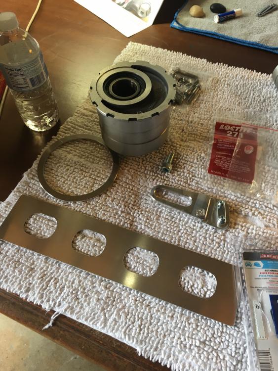
Thinking a simple home-made ally bracket will do and maybe I should stick bearings/bushings in the bolt holes? Not sure how I’m going to tackle that yet. 

#51
17 hours ago, Stray

So I’m not worried about aluminium corroding; more worried about hot water entering the sensors and damaging them. 

Is this a real concern or not? I know motorcycles can ride in the rain but hot soapy water is a different thing entirely. 

It IS a concern, though I don't know how much.

And the corroding is a concern.

Somewhere in the Honda manual it says to NOT use carb cleaner on the throttlebody as the bores are coated in a molybdenum something or other to prevent corrosion.  I didn't mention it because you're well past that stage, but yeah. Make sure to do anti corrosion.

Also very smart to do the o rings. Mine were a crusty mess. It's a 5th gen, and 20 years takes its toll on rubber, regardless.  They're a cheap, easy change if you have the throttlebody off anyway.

#52
Stray, 1/16/2019 at 10:07 AM

Here you go: https://rover.ebay.com/rover/0/0/0?mpre=https%3A%2F%2Fwww.ebay.co.uk%2Fulk%2Fitm%2F273649792185

He made this listing especially for me. If it’s no longer live just do a search for his other items using details in the title. 

Not yet, Gig.

Thinking a simple home-made ally bracket will do and maybe I should stick bearings/bushings in the bolt holes? Not sure how I’m going to tackle that yet. 

[image: IMG_4914.thumb.jpg.e331b54f4cd8bae63bcb0aa0f01df4c1.jpg]IMG_4772.thumb.jpg.ec7a688e232d1f67dccb9236cd51b4e0.jpgIMG_5006.thumb.jpg.8fbf92a83279b670c8405d61cea04a20.jpg

[image: IMG_5032.thumb.jpg.515524276b2985c85a6d17a89d6200a8.jpg]

#53

Looks like you have done a fine job getting those parts clean.

#54
Stray, 1/15/2019 at 8:24 PM

We run lots of aluminium items through the dishwasher without damage. Most modern frying pans are aluminium with raw bases - mine seem OK wash-after-wash. Same for baking trays and lots of other stuff - comes out the washer OK. 

So I’m not worried about aluminium corroding; more worried about hot water entering the sensors and damaging them. 

Is this a real concern or not? I know motorcycles can ride in the rain but hot soapy water is a different thing entirely. 

Most aluminum parts have anodized surfaces (clear) that won't be attacked too much in a dishwasher.  However, any part that has a nick or worn the anodizing (heck or clear-coat or powder coat) or coating away can easily corrode (surface) in a hot water and high pH dish-washer cleaning compound.  IF you run it without the cleaner--most likely the heat/steam/water will wash away quite a lot of grime.  IF you add the cleaning product--you do run the chance of corrosion.  Aluminum parts here in my washer --I see evidence of corrosion if the coating has worn away.

#55
zupatun, 1/17/2019 at 3:14 PM

IF you run it without the cleaner--most likely the heat/steam/water will wash away quite a lot of grime.  IF you add the cleaning product--you do run the chance of corrosion.

Do you think the sensors would be safe if I run TB through dishwasher without soap?  

#56
gig, 1/17/2019 at 12:39 AM

[image: IMG_4914.thumb.jpg.e331b54f4cd8bae63bcb0aa0f01df4c1.jpg]

Thanks Gig, I saw this setup on another thread and thought it quite clever. 

Except for two things:

1. how does that bracket stop the rear calliper from spinning towards to swingarm when the bike is wheeled backwards?  

2. The “slot” design is simple and elegant but allows for movement and vibration in use. That will take a toll on the fixing bolt and/or the slot over time, widening the clearances and accelerating wear. I can almost picture the torque arm “slapping” against the fixing bolt in use. In time one of the two parts will give way and the rear calliper will spin free, striking the back of the swingarm. 

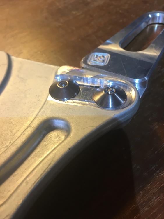
The OEM dogbone bracket only has holes, no slot, so it doesn’t allow movement/play. I’m thinking to make a shorter version of that, possibly with bearings, or rose joints and clevis.

Or just an ally bracket with two holes in either end...

#57

The Honda torque arms I'm familiar with (RC30/36/45/46) all use spherical bearings and 10mm bolts, except the NC35, which has some kind of slot arrangement.  

Ciao,

JZH

#58

This set up is on SS swing-arm Ducati's, and NC35. It does not move unless you spin the axel. I would imagine the pressure is concentrated on the caliper mounting points.   

#59

RVF400 only slides horizontally. 

#60
6 hours ago, Fastdruid

RVF400 only slides horizontally. 

I'm scratching my head over this:

[image: 1702569001786s7.jpg.01f2cad334443765a1a5c3f82ee9c5b0.jpg]

I guess it pivots a little around the cast bit on the swing arm, otherwise the hub would be locked in place!

Ciao,

JZH

#61

You know I hadn't considered it before...but you're right, it *has* to pivot slightly. 

Next time I take the wheel off I'll take a look (so expect a response about 2021 or so). 

#62
JZH, 1/21/2019 at 7:55 PM

I'm scratching my head over this:

[image: 1702569001786s7.jpg.01f2cad334443765a1a5c3f82ee9c5b0.jpg]

I guess it pivots a little around the cast bit on the swing arm, otherwise the hub would be locked in place!

Ciao,

JZH

Someone posted a picture to the FB group without the caliper bracket which reminded me of this before 2021... The cast bit on the swingarm *isn't* a cast bit on the swing arm. It rotates (part 12 below) 

[image: Honda MOTO 400 RVF 1996 RVF400RT Frame REAR BRAKE CALIPER]

Swingarm looks like this without it (and the hub etc).

[image: Image result for RVF400 swingarm -site:pinterest.com]

#63

Yes, that makes sense.  And saves me from having go out and look at the NC35 in my garage...  :wink:

Ciao,

JZH

#64
Fastdruid, 2/5/2019 at 4:29 PM

The cast bit on the swingarm *isn't* a cast bit on the swing arm. It rotates (part 12 below)..

That makes more sense. I couldn’t wrap my mind around it being fixed. 

#65

So I took a leaf out of Seb’s book and tried his Vaseline tip. 

No, not what you’re thinking! 

I smeared the tired plastic on my handlebar switchgear and dashboard with Vaseline and let it sit for a few days. Then I wiped it off with a crappy old microfibre cloth this afternoon. 

Here’s what they looked like before: 

[image: F863926B-6DA5-443F-955B-26F8E3500DF5.thumb.jpeg.d1eae8a869356479b11caa6535239ca2.jpeg][image: EAC2D302-DC2D-4D80-B013-CB60621F9A51.thumb.jpeg.23efce9644f5fe4d0420fce8a3e29a16.jpeg][image: 9EA19F3C-CB9B-4FD0-A666-628208A0E1E9.thumb.jpeg.6d20185c8af1de8d83ec916028a2c2c4.jpeg]

Then slathered generously with Vaseline: 

 [image: B9575BFF-362D-4E2F-9B46-341493334B11.thumb.jpeg.aa4bd900526cc711f5a8310708c491a9.jpeg][image: F1BA2845-77BF-4630-B838-B3B71D096416.thumb.jpeg.c56a2ce0be0f402618917a6e396aa6ef.jpeg][image: 9F8E55A4-B954-463B-9D73-25F0695B8972.thumb.jpeg.4572a8cb4e48e02335c82e683e4f9ae6.jpeg]

Then Vaseline wiped off to reveal a slightly more rejuvenated surface: 

[image: 7D395AB2-AF84-41ED-B27B-5103E901588B.thumb.jpeg.6e5c10c49d200f5892258dab706f673e.jpeg][image: C06ABF58-36F6-425B-AF08-3648074F4354.thumb.jpeg.f1a19f1b332495f11796427051b3339f.jpeg][image: 43B61426-E0EB-4C11-99A4-2E503FD8FE68.thumb.jpeg.33a190f70c63cddf37ae5b1a863beec0.jpeg]

Looks a bit better I think. More satin than matte. Vaseline had begun to skin-over after about a week but wiped off easy enough. Let’s see how long it lasts. 

Thanks for the tip, Seb - I’m a believer! 

Stray

#66

Started playing around with the Triumph Daytona 675 rear subframe and tail section this afternoon. 

Didn’t have a great deal of time and most of it was spent hammering the subframe straight! Did you ever regret buying something on eBay? 

Once that was done I had to fit the fuel tank (full of fuel) onto the bike for measurements and looks. So how does one do this without pi$$ing fuel all over everything? Well I cut up some spare bits of silicone hose and clamped them shut with zip ties: 

[image: 3C0D4548-7C69-45BF-9291-86B6567271C5.thumb.jpeg.d977c454186e115b101177fa56a3097b.jpeg]

A wide piece of silicone tube was cut to go over the fuel line hose: 

[image: F26D6FF5-76F9-4A8A-8BE7-B6C08D2C23F5.thumb.jpeg.24e86dc315335cf2a1c30f5277fd983f.jpeg]

Managed to snap a few pics of the “stance” with this new tail. 

Shoved in tail: 

[image: 4C47F7FE-0193-4286-9EB2-7D8752FEBADE.thumb.jpeg.ef9431d80b27522ec6efc3aeb46a4ce4.jpeg]

High tail: 

[image: F7D1993E-7D15-4D16-AD40-3C3888DBE930.thumb.jpeg.81595b77efb7fdd14efd0b02f092d885.jpeg][image: 14508551-D3A6-44F0-9DA9-7F0CF9B47644.thumb.jpeg.8adabc35e66c48fab6e885894bf24c30.jpeg]

Lower tail: 

[image: 1AEE01CF-81C9-46A7-AE77-58C6E72B79DE.thumb.jpeg.08872039f3c544b2d95db361f77a88e4.jpeg]

[image: 4C7BE356-AEE3-4348-AFE3-0574F627D21B.thumb.jpeg.63c2609c47a38f9e9cc76cd9e9a036d6.jpeg]

Note that the subframe needs to be moved 10mm closer to close the gap between tank and seat. Subframe is sticking out 10mm too far back, so when finished it will end roughly where the end of the black seat cowl is now. 

Here’s a pic of the gap that needs closing: [image: 90F85F59-ABC6-4D45-B07F-A27AC2C4DB55.thumb.jpeg.5aaa612ea7d29e5f3a8f1fa203345b68.jpeg]

What do you guys think? I’m leaning towards the Lower tail look. Makes rear cowl and tank line up parallel. Tail also plays well with knee cutouts in tank. 

Am am I seeing this right? 

Here are the dimensions that need squaring if anyone is really bored...

  1. Daytona 675 07-12 subframe is 97mm too long on the bottom rail - need to cut rail 97mm shorter. 
  2. Top rail is 132mm too short - needs to be lengthened by 35mm (132-97mm).
  3. Width at top of Daytona 675 subframe is 166mm (outside) but needs to be 154mm (VFR top mount inside) - needs to be pinched closer by 12mm
  4. Width at bottom of Daytona 675 subframe is 195mm (inside) but needs to be 222mm (VFR bottom mount outside) - needs to be spread out 27mm

Best, 

Stray

End of thread · 66 posts recovered Wayback Machine snapshot 20 Sep 2019