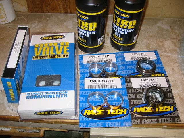
I installed new Race Tech rebound and compression valves in my forks yesterday and put in new bushings and seals. My bike has clicked over to 55,000 miles so it was high time to rebuild my forks. I usually just freshen up the oil but this time I thought a complete rebuild was in order, along with new valving to make my bike handle better.
The Parts
Parts List Below
- Race Tech Fork Gold Valve (compression)
- Race Tech Fork Rebound Gold Valve
- 2 quarts of US-1 ultra slick fork oil (5w)
- Pair Fork Bushings Inner
- Pair Fork Bushings Outer
- Pair Showa Oil Seals
- Pair Showa Dust Seals
- Paul Thede's Technical Edge Video
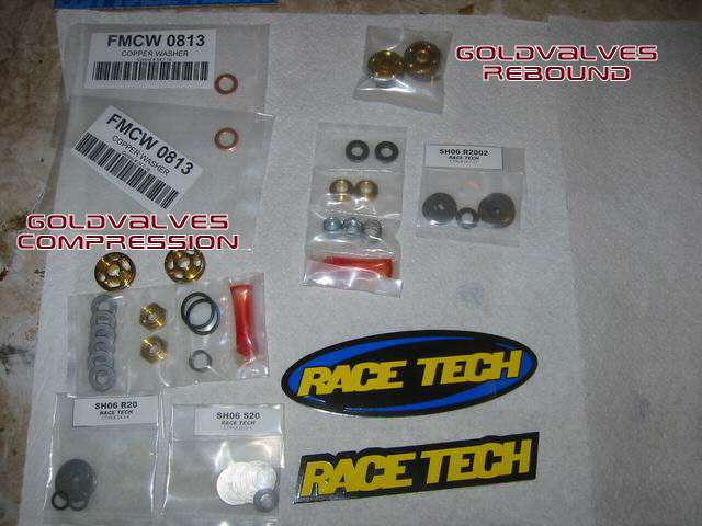
Here is a closer look at the parts that come in the kit.
All the parts are ordered separate but they give you a complete list on the website of what you need to rebuild your forks properly and valve them to your needs. Shown here are the two sets of valves labeled in the picture, many of the parts are for different types of cartridges, Showa, KYB. So there are parts you will not need or use. They sent me 3 sets of various shims to sort through, check valve springs, cupped washers with built in sleeves, O rings, baseplate shims, check valve shims, nuts, and thread lock compound.
Oh and a boat load of Race Tech stickers, I have them all over my computer now.
NOTE: I already had Race Tech springs installed from Last year, if your going through all the trouble of rebuilding your forks getting fork springs rated for your style and weight is a must - Here is the link to the Race Tech Spring How-To
Prep Work - Getting Started
[image: Posted Image]
Loosen the Clip on Bolts and remove them out of the way
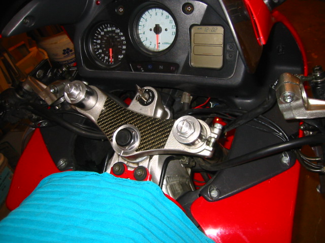
Pull off the clip ons
[image: Posted Image]
Marking fork height
Here is a tip - take a piece of paper and mark your set height on the forks, it is easier than remeasuring, especially if you have lowered them and like the way they are.
[image: Posted Image]
[image: Posted Image]
If you don't own a vice than use the one available too you its already there - your own triple clamp, loosen the fork cap.
[image: Posted Image]
Remove the front fender 4 @ 5mm
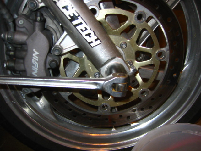
Remove the axle bolt 21mm
[image: Posted Image]
Remove the caliper bolts right side 2 @ 12mm
I have a bunch of plastic buckets I use to toss the parts in so I don't loose them, some guys put them on a paper towel and sort them out, whatever you do just don't kick them under the counter like I did, PITA!!
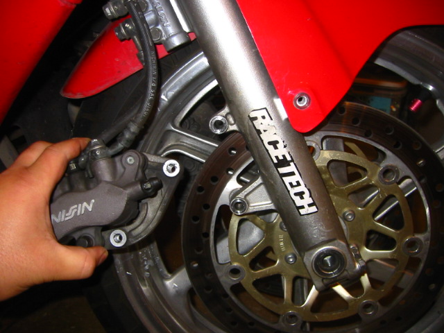
Gently slide the caliper off the brake disk DO NOT TOUCH THE BRAKE LEVER WHEN THE CALIPERS ARE OFF or it wont go back on easy
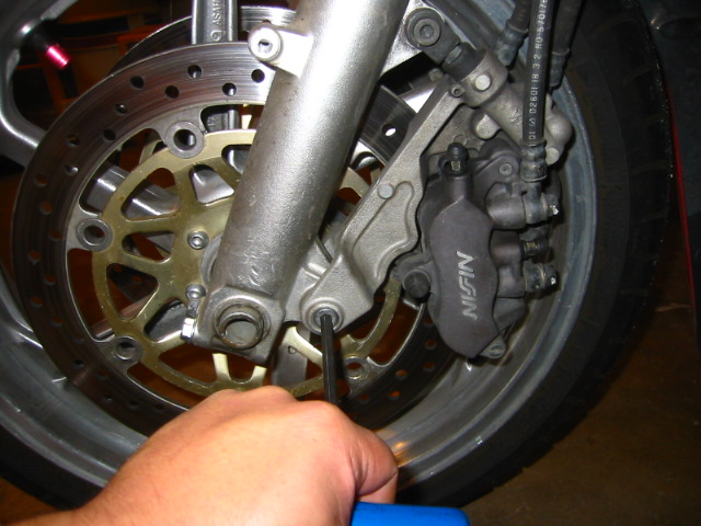
Remove the Allen bolts on the Linked Brake System, notice the secondary master cylinder at the top that is what activates your rear linked brake. 2 @ 6mm remove the caliper.
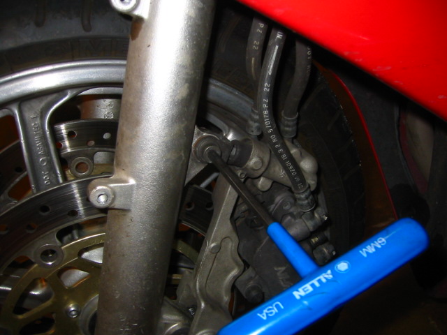
It is easier to start with this bolt first but I cant ever seem to remember that, it will try to lift the whole caliper as you turn otherwise. These Allen bolts often freeze on from the heat of the brakes being used.
I would suggest buying the service manual for specs on torque settings, and more detailed procedures of removing these parts. It is an invaluable source of information.
[image: Posted Image]
Take the time to inspect your bolts, every time these are removed and retorqued the bolt gets stretched, this one is shot as you can see the threads are stretched I will need to replace all these caliper bolts.
[image: Posted Image]
Loosen but don't remove the 4 axle pinch bolts 4 @ 12mm total both forks
Now I have loosened or removed the bolts before raising the wheel. I prefer not to go torquing on bolts when the bike is suspended by a jack.
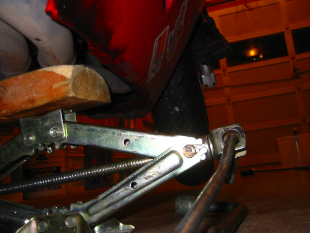
Rasing the front wheel is easy just a block of wood under the headers and a jack, with the center-stand down, it is stable. Just as it is spelled out in your owners manual
[image: Posted Image]
I use a rod and rubber mallet to punch out the axle careful not to damage the inner threads or peen the soft axle metal so the bolt wont go back in (note I no longer do it this way - use a screw driver threaded through the holes in the axle - pull it out by twisting and gently pulling the axle out)
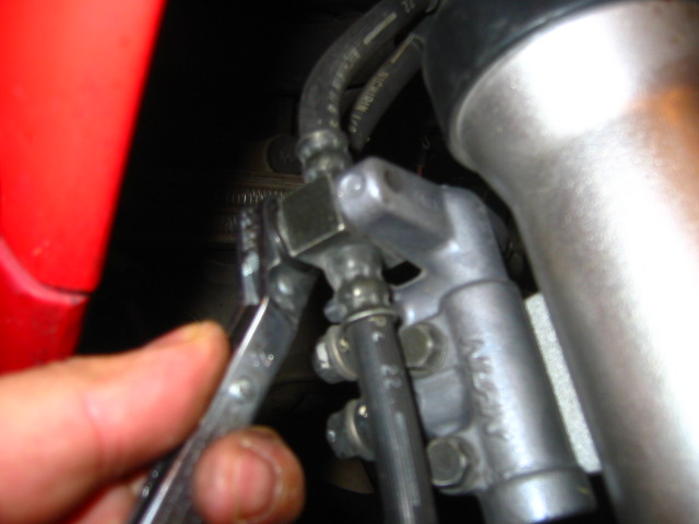
Unbolt the brake hoses, start with this one cause the hose is in the way of the other two hanger bolts, 4 @ 10mm total
[image: Posted Image]
Swing the hose out of the way and remove the brake line manifold
[image: Posted Image]
The picture is moved out a bit so you can see the placement of the brake-lines
There is no need to remove the fairings unless you want more working room, I did not but its up to you.
[image: Posted Image]
Reach up with a wrench and loosen the lower triple clamp bolts on both sides 2 @14mm these are really cranked on, I use a pipe over the handle of my wrench for a bit more leverage.
[image: Posted Image]
Loosen the upper clamp bolts now and begin to slide the forks out one by one out the bottom.
NOTE: if you do not own a clamp you can use the triple clamps here to pull out the cartridge, loosen the bolt at bottom and let the oil drain out the bottom then pull off the fork cap here. I would find a vice if you can that has aluminum jaws that wont mar the forks, I don't so I used some soft wood.
[image: Posted Image]
After you loosen the top clamp it should practically fall out.
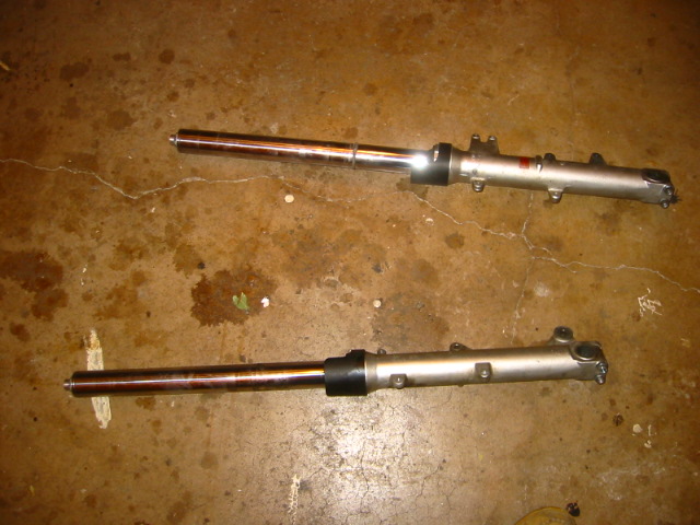
Make note of which fork goes on which side, a label on some masking tape will do nicely. I am quite familiar with them so I did not.
REBUILDING THE FORKS
[image: Posted Image]
Remove the bottom fork bolt careful not to lose it, notice the baseboard I used to clamp the forks in so they did not mar the metal. This was also the step I mentioned earlier about doing while still clamped to the bike.
[image: Posted Image]
With the bottom bolt out you should be able to pull out the whole inner assembly after you screw off the fork cap, it will be oily so have some paper towels or rags available to clean up, put them in your oil pan.
Note: it is easier to do this job with the fork cap already loose, I do that as soon as I remove the clip-ons with the forks clamped in the bike triple tree. I also screw the preload out all the way so that the top does not protrude out at all.
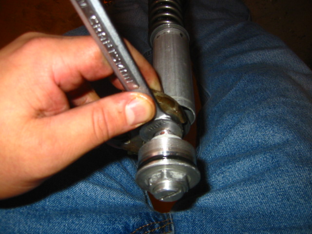
Remove the fork cap from its pinch bolt 2 14mm wrenches should do the trick, back the preload all the way out while loosening the fork cap first this moves the cap out of the way of the pinch bolt and you can get enough clearance for the two wrenches, otherwise the cap covers up the wrench flats.
[image: Posted Image]
Lay out the parts in order as they come out.
NOW IS THE TIME TO CLEAN ALL YOUR PARTS! With a solvent of some sort to remove any grime or metal bits that could destroy your valves, o-rings, oil seals and such.
Note: that little zip tie on the fork tube helps me set my sag when I am alone I tossed it and will put on a new one when I go to reset my sag.
The Oil lock actually fits on the end of the cartridge and gets bolted with that bottom bolt you removed. You must remove the Oil Lock from the Cartridge in order to complete the work, it just slides off but may be full of junk. Also if you have trouble with that bottom bolt then the cartridge is spinning along with the bolt, it helps to pull on the damping rod to get a little tension on the bolt so it will remove instead of just spin while removing it from the fork.
Replacing bushings and the oil seal
Clamp the fork somehow so you can work on the thing, a vise is invaluable here If you don't have one I suppose you can leave it clamped on the bike but make sure the bike is secure so you can pull on it without falling over, again using a vice with aluminum jaws are best.
[image: Posted Image]
I tapped on the fork protector until it popped off
[image: Posted Image]
pry off the old dust seal, it may be reused if you inspect it and its looks good. I just replaced all that stuff
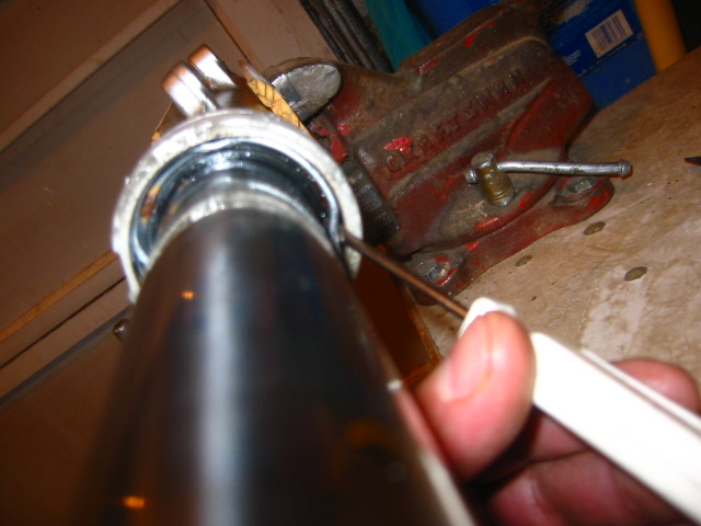
Remove the metal retaining clip
Now here is the fun part, make sure the fork bottom is firmly secured in your vice or whatever your using to hold it firm yank on the fork tube a few times until the whole thing comes out, like a ram rod.
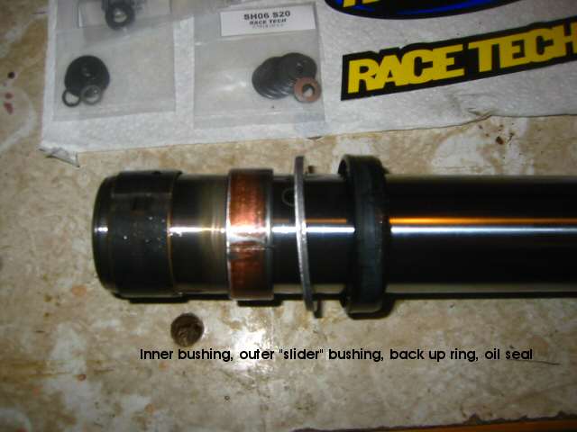
Fork tube is removed displaying the two bushings, back up ring, and the oil oil seal.
The only part I decided to reuse was the back up ring, the bushings had the protective Teflon worn away and the oil seal had actually cracked and spring inside rusted a bit. The oil seal has two coiled springs that wrap around it to provide wiping tension on the seal. The busing are split down the side so they are easy to remove, push a flat head screwdriver in the gap and pry it apart then pop them off. The oil seal just slides off.
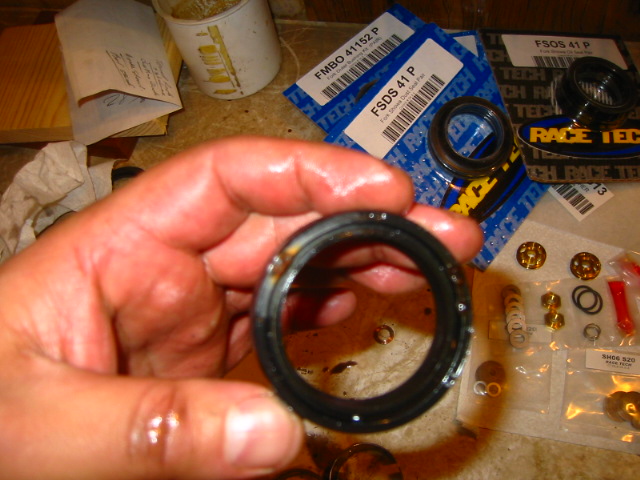
You can see the crack in my seal and the rust, no wonder why I could feel every bump in the road the oil seal would not slide correctly on the fork tube.
You should also inspect your fork tube for out of round and any nicks or rock pits, sand them out smoothly with 400 grit or better sandpaper to remove any sharp edges that would destroy your new seals. If its bent or nicked up too badly replace the whole thing. Paul instructs in the video to use a couple of V Blocks and a dial indicator, or roll the tube over some plate glass and check for gaps with a feeler Gage. Mine had a few rock dings so I sanded them out, mostly way up at the top where the fork hardly ever gets too.
[image: Posted Image]
You can see the Teflon has worn off the sides but the inner bearing looks good, replaced it anyway. This bearing sits inside the recess on the fork tube.
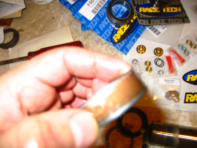
The upper slider bearing was completely trashed, the Teflon had come off pretty much evenly over the entire leading edge of the surface.
If there are large chunks of Teflon missing on your bearing that could indicate a dent in your fork tube.
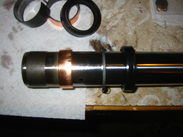
Slide on the new parts
Paul instructs on the video that before sliding on the new oil seal, to cut the end off a plastic bag and fit it over the fork tube to keep the seal from being damaged as you slide it over the inner bearing recess. Me I just popped it on from the other side and avoided sliding it over the recess. Make sure you put it on the right way and not back-wards. There is printing on the side that shows up, the non printed side goes down or inside the fork bottom. You should take note of this as you remove the old parts.
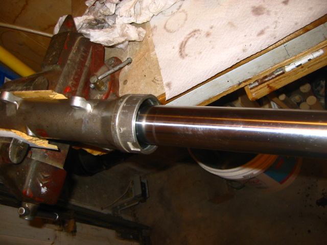
Push the parts in as far as they can go, then you will need to drive them in.
Race tech sells a fork seal driver, he drives in the bushings first then the oil seal, using the driver on the back up ring first then drives in the seal. I do not have that fancy seal, you can find a pipe of the right diameter to drive it in but I could not find one either so I just used the old oil seal at a driver and tapped on it with a hammer making sure to go around the entire surface and not drive in the seal crooked and ruin it. I put some plastic on the fork tube so I would not scratch that as I tapped the oil seal in.
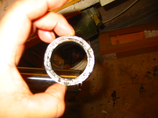
Slide the old seal on as a driver
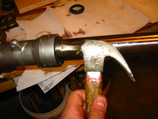
Here I am tapping the seals in I could not get the plastic to stay on as I took the picture, but you need to be careful not to damage the fork tube or the seal by going at it too hard. You need to tap in that seal far enough to get the retaining clip back in.
The dust seal and the fork protector just slide on finger tight, there is a notch on the protector that slides into a groove on the fork bottom make sure to line them up first and tap it on gently with your hammer.
Re-valving the cartridge
[image: Posted Image]
You should be able to push the bottom of the cartridge in with your thumb, this reveals the retaining clip.
[image: Posted Image]
Remove the retaining clip gently you can break it pretty easy if you manhandle it.
Now you can push on the damping rod and the compression valve should pop out the end.
[image: Posted Image]
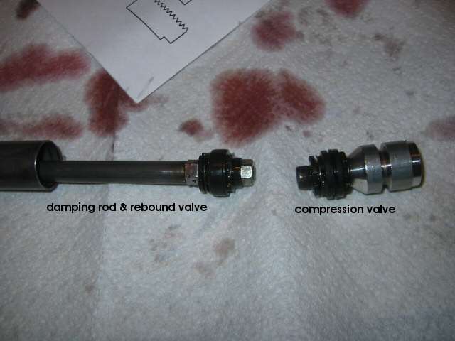
This is how they are oriented as you push them out the bottom of the cartridge.
[image: Posted Image]
Closeup of the compression valve stock form. look at the flimsy shim stack, those shims were so thin, like .08 mm in thickness and not as many as Race Tech calls for.
[image: Posted Image]
The rebound valve on the end of the damping rod.
[image: Posted Image]
You will need to clamp on the body of the compression valve in order to remove the retaining bolt, this one is an Allen bolt, 5mm and it was on tight with lock-tight. You must be careful not to damage the body or it wont go back into the cartridge, I ended up clamping on the very end where it was recessed to get enough clamping force to hold it firm enough.
[image: Posted Image]
A digital micrometer or a tool like this is invaluable for sorting shims, I bought this one for $20 bucks at Harbor Freight tools
I took apart the stock valve and laid out the pieces in order on a paper towel and determined that I would need to reuse the base plate, and the cupped washer with the built in spring washer and of course the Allen bolt the rest I would use from the Race Tech kit.
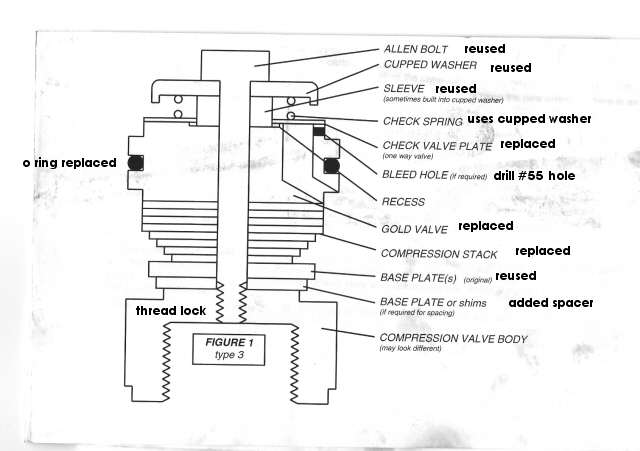
Here is a diagram of how the compression valve is set up.
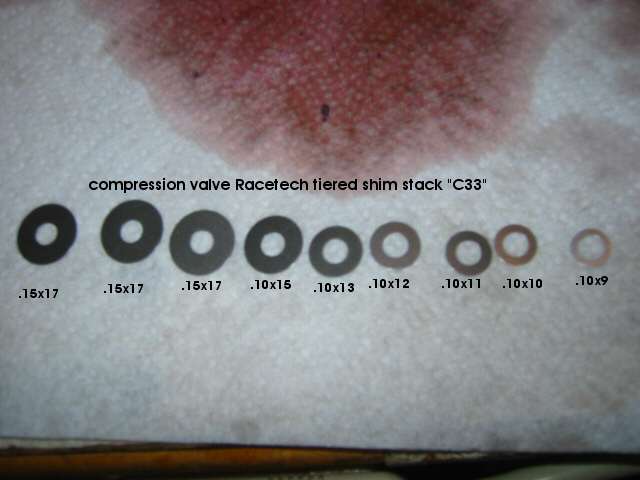
Here is the custom valving stack recommended by Race Tech it consists of the shims displayed.
There were several shims to sort out in the kit and I sorted and measured them all. These shim kits are designed to work with the gold valves so trying to use them with the stock valves would net a bad result, they are thicker than stock and there are more of them. Basically Race Tech has 10 recipes for street applications of shim stacks which vary the number of.15x17 shims used and create a different stiffness profile. I used the c33 recipe layed out in the picture. It is a tiered stack that is supposed to give you a bit of flexibility with high and low speed damping, the speed pertaining to how fast the wheel travels up and down as it rides over the road, it is tired so you get more damping at low speed and less at high-speed. flexing those shims in an ever decreasing manner as it encounters then next shim. The faster the fluid travels though the ports the more the shims flex to let the fluid though the slower the less they flex so you have a tunable valving set for how you bike handles.
Race Tech provides you with a code that you can plug into their website to get the custom shim stack you need.
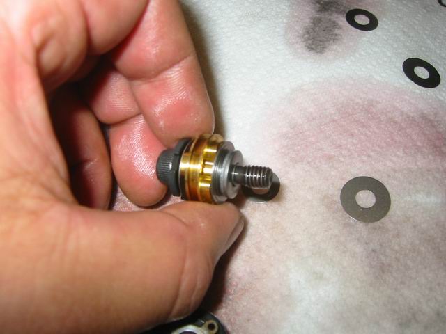
Here I am putting the shims on after I placed the gold valve in
There is a recess on the top of the gold valve that fits neatly onto the sleeve of the "top hat" or cupped washer, this one has a built in spring washer but you have to make sure that the sleeve clears the check valve plate and does not sit on it cause that check valve must float freely or else you ruin your ride.
The check valve plate looks just like any other shim but it is thicker and it has a bigger hole in the center to accommodate the thickness of the sleeve. Make darn sure your check valve plate is free!
:media:
Check valve inspection video
I made this little movie to demonstrate how the check valve must float freely if you cant move it with your fingers then the sleeve is most likely clamping it down and you will have to take it apart to free it. I used a replacement instead of reusing this one. Make sure the sides of the valve sit flat with the plate, sand the valve with some 400 grit paper if there are nicks on the valve. The video from Race Tech explains to use a plate glass and sand the valve in a figure 8 motion till its perfectly flat.
[image: Posted Image]
Locktight the threads, then screw it into the body, torque the bolt to 30 INCH pounds, or 2.4 FOOT lbs. Its not much!
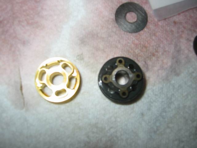
Here is a side by side comparison of the two compression valves note the small holes of the stock one. Most of the valving action is done by the shims on the Race Tech version
[image: Posted Image]
since the fork is non adjustable you must drill a small bleed hole into the gold valve, pointed out where in the drawing above.
Race Tech calls for a 1.3mm hole to be drilled into the valve to bleed the valve. This is done with a #55 drill bit that are hard to find, I had to go to a hobby shop to find one. One of those places that sell model trains and such, they had them for cents a piece. For racing they say to use a #53 drill at 1mm.
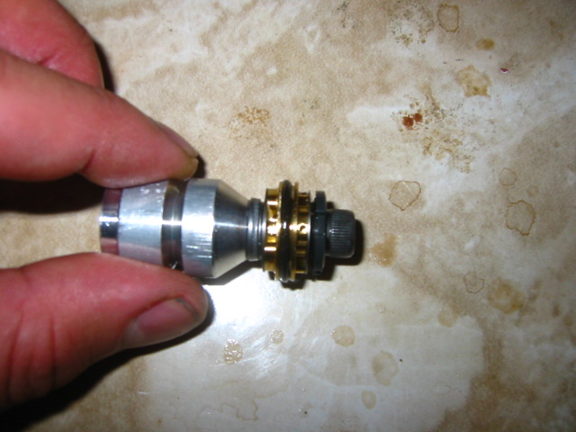
You can see the bleed hole on the right side of the O ring, it is necessary otherwise your bike will not be damped correctly. Make sure to clean out the metal bits and blow it out. Its important that the parts be clean of any grime and metal bits
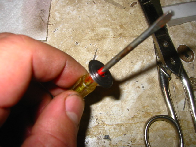
Here is a tip from the Race Tech video, sort out your shims and store them this way for your next fork
Rebound Valves
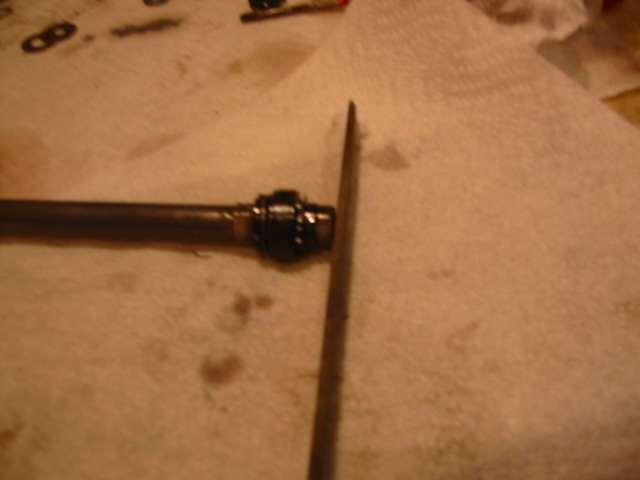
The end of the rebound bolt is peened over at the factory so you have to file it flat to get the nut off easy.
[image: Posted Image]
Time to get serious, Dremel tool and safety glasses!
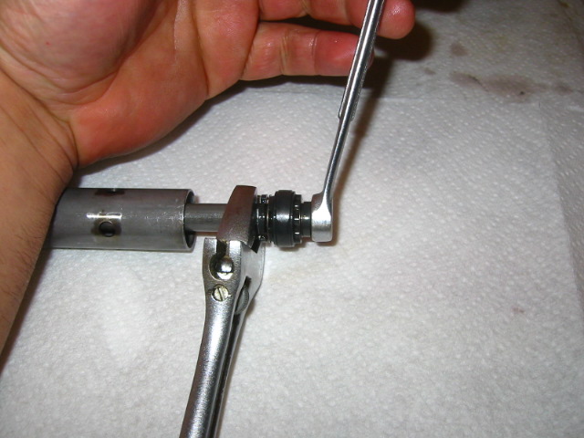
Now you should be able to get the nut off, 10mm nut
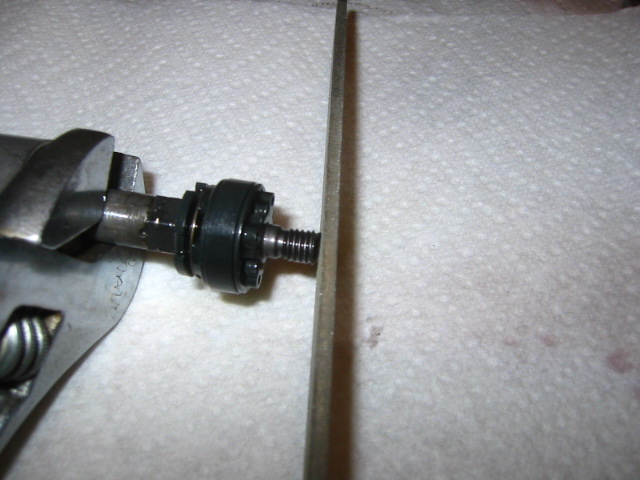
Chamfer the end to get the new bolt on easy
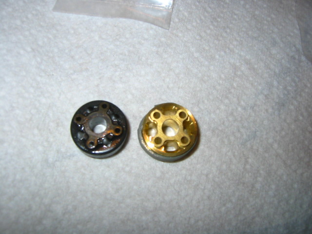
Compare the rebound valves, notice the large gray Teflon band on the new gold-valve
Rebound gold-valves use a bigger shim stack than the compression valves 11 shims most of them are .15 x 17 and this stack is also tunable, Race Tech determines this by the spring rate of your fork spring. They give you an array of spring rates and a formula to determine how many shim to put on, its pretty simple. This is based on only the spring rate and not how fat you are heh :goof: I had the r20 recipe that uses 10 @ .15 x 17mm shims and 1 @ .10 x9mm shim. The formula takes into account the oil weight and the rate of the fork spring, and diameter of the damping rod, ours is a 10mm rod. You get a nice little cheat sheet to figure it all out with.
[image: Posted Image]
Flipped over
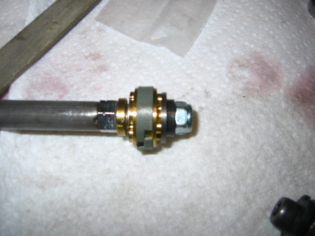
Here I used mostly new parts with the exception of a spacing shim near the bolt. New bolt too also torqued to 30 INCH pounds and treated with locktight.
[image: Posted Image]
Here I am drilling a #55 bleed hole into the rebound valve.
[image: Posted Image]
You must also drill a hole into the rebound valve since it is not adjustable, again 1.3mm or #55 drill bit size, these bleed holes are oriented to face the inside chamber of the cartridge. Make sure you blow out the metal bits and clean it up.
Slide the valves back in the way they went in and put in the retaining clip. Put the oil lock piece on the bottom and slide it into the fork tube, then put on a new copper washer on the bottom fork bolt and tighten the cartridge to the bottom of the fork.
Fill the oil level of the fork to 120mm after pumping the damping road to bleed the air out of the cartridge until you feel resistance, make sure the fork tubes are compressed when filling the fork oil to level.
Here is a better description of how to fill the oil level - Cartridge Fork Service Thread
Everything pretty much goes back on the way it came off, don't over-tighten the fork cap to the fork tube it only needs 6ft/lbs but the pinch nut and fork cap inside should be 14ft/lbs
Set your sag correctly 30 - 35 mm.