VFRDiscussion ARCHIVE / READ-ONLYREAD-ONLY

2007 Vfr800 Rwb Dead At Key Turn!

90 posts Started 14 Oct 2014 Last recovered post 5 Feb 2015 Wayback Machine snapshot 18 Jul 2017

#1

Hey everyone! Went to start my VFR this morning and as I'm turning the key on zero, zip, nada! No noise from the injectors, no running or dash lights. It is currently my only transportation. I thank god this didn't happen when I was on the road!! I took the battery down to Autozone and it tested good. I have a green translucent fuse to the right of the battery and it's fine. I'm at 28,900 miles at this point and currently there are really no mods that tie into the battery to speak of. I'm, not a mechanic but I can follow instruction and review pictures for info.. I am aware of many electrical issues with these bikes. If anyone can refer me to a troubleshooting protocol or some step by step troubleshooting I would be much obliged!

P.S. I've smelled a funny burning smell (hair like?plastic?) when on the road sitting at lights on occasion but dismissed this as being a zip tie I have on the lower cowl by the pipes.

Barry,

Austin TX

#2

Is the clock working? I'd check the wiring/starter relay/etc next to battery for crispiness or shorting. There are two main fuses, one on top of the relay and the other inside a small plastic connector looking thing. Next you'll want to pull the right lower fairing and check the connectors coming from the R/R mounted at the front right of your frame. The connectors will be just above the right radiator. The wiring from the R/R to the connector is yellow.

#3

And then go ahead and order a stator and R\R.

#4
dutchinterceptor

Is the clock working? I'd check the wiring/starter relay/etc next to battery for crispiness or shorting. There are two main fuses, one on top of the relay and the other inside a small plastic connector looking thing. Next you'll want to pull the right lower fairing and check the connectors coming from the R/R mounted at the front right of your frame. The connectors will be just above the right radiator. The wiring from the R/R to the connector is yellow.

The clock is working. Does that rule anything out? What is the R/R??

Switchblade

And then go ahead and order a stator and R\R.

What is the R/R?

#6

Badelman -- well unless you wanna spend bucks at the dealer, the first thing to do is go buy a multimeter, they are near everywhere, autozone, harbor freight, etc. Once you got that, the troups here can start pointing what's next. Welcome to the wonderful world of VFR electrics. The system is a 4 legged stool, battery, harness/connectors, stator, R/R.

:cool:

#7

I guess this and other recent posts dispel the notion that Honda "fixed it" with the wiring changes from 2006 forward (on 6th gens) . . . :dry:

#8

I'll get a multimeter tomorrow. Don't really know how to use one but I will read about. At what points do I check (At battery, harness/connectors, stator, R/R (What's RR?)?) and what do I hold the black one on and then the red?

Thanks!!

#9
badelman

(What's RR?)

Regulator/Rectifier

We'll walk you thru using a multimeter. Can you touch two index fingers together? You're qualifiied... :smile:

#10
mello dude
badelman

(What's RR?)

Regulator/Rectifier

We'll walk you thru using a multimeter. Can you touch two index fingers together? You're qualifiied... :smile:

Thanks for the encouragement Mello! OK, got the multimeter from Autozone (detail here).. What's the next step?

#11

So lets backtrack and see where you are at. Some get ready steps.

-- The bike is totally dead now or the fuel pump comes on at key/kill switch on?

-- Locate the fuse box and the starter relay/fuse. -- Will a 6th gen guy jump in on this one, I'm mostly a 5th gen guy.

-- Look for blown fuses, note where they are. Find replacements.

--- Get the multmeter out --- Set on DC volts, my guess there is couple selections to set it at. Go for 20ish..---what is the battery volts?

--- Red on positive, Black on negative.

--- Pull right side body panel.....

--- You will see near up front on the frame a big ass finned gray box - that is the R/R. - Find the 3 yellow wires from that going to the rear and find the connector that the yellow wires go to. -- Pull apart and see what it looks like.

Thats a start, we'll go from there. If you have a camera to take an occasional pic, that would be helpful.

md :cool:

#12

There is a fuse box under a fairing panel that attaches to the right side of the instrument cluster trim panel, and to the 'nose cowl'. I think there are 2 of the allen screws and one push-pin fastener involved. This little panel is a PITA to pull off, you feel like you're going to break something getting it loose. I'm @ work and going by memory, but I also have the '07 RWB model, and that's where my fuse box (may not be the only one) is. It's also up where the diagnostic connector is, above & in front of the R/R. Never had to look for the starter solenoid, so I can't help locate it ...

ACE

#13

Yes.. bike is totally dead except the clock on the dash is working. I drove it two days ago with zero issues. I'll be able to work on it tonight and I will post updates feverishly! Thx guys!

#14

Ok, got the seat off. Battery is a YTX9-BS. It says on the top STD: 0.9A X 5~10h or QUICK: 4.0AX1.0h. Also, I got the multimeter black plugged into the COM hole and the red plugged into mA BAT hole with the ohm shape. There is another hole labeled DC 10A. Should I have the black in that one instead?

Also, on the multimeter.. theres a DCV V section (goes from 200m then 2,20,200 and 500) and a small section that just says DC10A. Which one should I switch to?

I feel dumber than a stump on this stuff!

Edited October 15, 2014 by badelman
#16
Switchblade

https://www. electrosport.com/media/pdf/fault-finding-diagram.pdf

Try this it mite save you a lot time .

http://www.electrosport.com/technical-resources/diagnosis-center/fault-finding-guide

The fault finding diagram is awesome and even helpful with setting up the multimeter although I'm still confused as to which hole on the multimeter I plug the red lead into! Which one?? Also a little confused about what I can and cannot do on the diagram with the engine not starting or vfr not turning on at all. I do see the section regarding turning the bike off but can I do all tests at the start without the bile being on at all? Should I at least turn the key on even though nothing happens? Thx!

Edited October 15, 2014 by badelman
#17

Generally you never use the Amp reading side of a voltage/ohm meter. For just about anything anyone here will recommend, you want to have the red lead to a Voltage port on the meter. Black to COM is correct for operating the meter.

Set the DVOM for 20V DC.

#18

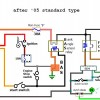
Here a pic that a member posted.

VFRwiring


Guess it really does not show the charging system but if it happens not to be the charging system it's good to have !

#19
badelman
Switchblade

https://www. electrosport.com/media/pdf/fault-finding-diagram.pdf

Try this it mite save you a lot time .

http://www.electrosport.com/technical-resources/diagnosis-center/fault-finding-guide

The fault finding diagram is awesome and even helpful with setting up the multimeter although I'm still confused as to which hole on the multimeter I plug the red lead into! Which one?? Also a little confused about what I can and cannot do on the diagram with the engine not starting or vfr not turning on at all. I do see the section regarding turning the bike off but can I do all tests at the start without the bile being on at all? Should I at least turn the key on even though nothing happens? Thx!

Badelman, I'm gonna go out on a limb and say put the red lead on the right port on your Voltmeter. Mine has -- V(ohm)mA on that port, the 10A max is the other one. ------ -The trouble chart is not gonna help at this point, I like a simpler test procedure. But first you have to get it to run.

Switchblade

Here a pic that a member posted.

Guess it really does not show the charging system but if it happens not to be the charging system it's good to have !

Nice pic Switch, that 'll help....

--- Question for the Brain trust... isnt a battery YTX9-BS damn small for the bike? Shouldnt it be something like YTX12 OR YTX14?

#20
Switchblade

Here a pic that a member posted.

Guess it really does not show the charging system but if it happens not to be the charging system it's good to have !

Thanks Switch!

pres589

Generally you never use the Amp reading side of a voltage/ohm meter. For just about anything anyone here will recommend, you want to have the red lead to a Voltage port on the meter. Black to COM is correct for operating the meter.

Set the DVOM for 20V DC.

Thank Pres.. This is helpful. I dont have DVOM but think it may be the same as DCV V?

mello dude
badelman
Switchblade

https://www. electrosport.com/media/pdf/fault-finding-diagram.pdf

Try this it mite save you a lot time .

http://www.electrosport.com/technical-resources/diagnosis-center/fault-finding-guide

The fault finding diagram is awesome and even helpful with setting up the multimeter although I'm still confused as to which hole on the multimeter I plug the red lead into! Which one?? Also a little confused about what I can and cannot do on the diagram with the engine not starting or vfr not turning on at all. I do see the section regarding turning the bike off but can I do all tests at the start without the bile being on at all? Should I at least turn the key on even though nothing happens? Thx!

Badelman, I'm gonna go out on a limb and say put the red lead on the right port on your Voltmeter. Mine has -- V(ohm)mA on that port, the 10A max is the other one. ------ -The trouble chart is not gonna help at this point, I like a simpler test procedure. But first you have to get it to run.

Switchblade

Here a pic that a member posted.

Guess it really does not show the charging system but if it happens not to be the charging system it's good to have !

Nice pic Switch, that 'll help....

--- Question for the Brain trust... isnt a battery YTX9-BS damn small for the bike? Shouldnt it be something like YTX12 OR YTX14?

Mello, ok.. I got the red lead in V(ohm)mA BAT (right port) and black lead in the COM port. I'll turn the switch to DCV V 20 for testing. Where to go next? You say I have to get the bike running first?? Where to start?

Switch, I don't understand your diagram yet but sure it will start to make sense once I start digging in!

#21

Seems like somebody on here had an issue like this where their starter switch was stuck. It would be easy enough to check that by separating the switch unit and hit it with a bit of wd-40 or contact cleaner.

#22

I'm with mello dude - that YTX9-BS is the wrong battery for the bike. Yuasa lists it at 120 CCA (cold cranking amps). The factory battery is YTZ-12 which is 210 CCA. At its peak what you have is barely adequate so it may be just too tired to do much more than run the clock.

If it were me I would get a fresh battery of the correct type installed before I went any further. You may find that you just have a very weak battery. Since you have the meter (and set to 20v DC), place the leads on the terminals (red to +) and see what you get.

#23

My clock kept resetting when my battery was going dead on my '07. If yours is doing that, I would look at the battery again. I always start with the easy stuff. You did mention that Autozone checked it, but just to be safe... besides I agree with Cogswell and Mello Dude that the YTZ-12 is the way to go.

#24
Cogswell

I'm with mello dude - that YTX9-BS is the wrong battery for the bike. Yuasa lists it at 120 CCA (cold cranking amps). The factory battery is YTZ-12 which is 210 CCA. At its peak what you have is barely adequate so it may be just too tired to do much more than run the clock.

If it were me I would get a fresh battery of the correct type installed before I went any further. You may find that you just have a very weak battery. Since you have the meter (and set to 20v DC), place the leads on the terminals (red to +) and see what you get.

I'm with ya Cogswell, the battery size caught my eye imediately...... Badelman, sorry man, go get a YTZ - 12 or 14 battery.

- Good point Dutch on the the switch unit....

#25
mello dude
Cogswell

I'm with mello dude - that YTX9-BS is the wrong battery for the bike. Yuasa lists it at 120 CCA (cold cranking amps). The factory battery is YTZ-12 which is 210 CCA. At its peak what you have is barely adequate so it may be just too tired to do much more than run the clock.

If it were me I would get a fresh battery of the correct type installed before I went any further. You may find that you just have a very weak battery. Since you have the meter (and set to 20v DC), place the leads on the terminals (red to +) and see what you get.

I'm with ya Cogswell, the battery size caught my eye imediately...... Badelman, sorry man, go get a YTZ - 12 or 14 battery.

- Good point Dutch on the the switch unit....

I used the multimeter on the battery and got between 12.60 and 12.61. How does this look?

Group consensus works for me I can still replace the battery but does it look to be the immediate issue or cause of dead bike even though it tested good at the Autozone with this reading? Are you thinking that it will just start right up after being replaced? A little history on the battery: The guy I bought it from put this battery in new just before I bought the Viffer from him. I asked if anything was wrong before that or if there was a reason to change the battery and he said .....nope. I believed him as I do go riding with the guy, he lives close and has about 6 other bikes.

P.S. Clock is not resetting..

Per starter switch being stuck: Do I just dismantle the starter switch to see if it's stuck? Wouldn't at least the running lights come on or something even IF it is the issue (don't recall what comes on and what doesn't or shouldn't).

Edited October 15, 2014 by badelman
#27

I know the starter switch kills the headlights for sure but can't remember if anything else cuts off. The clock being on shows that you are at least getting power to the meter panel.

Switchblade is right though, check the obvious stuff first. If the battery tests at above 12 volts and was load tested at Auto Zone I wouldn't swap it just yet.

  • Make sure all of the fuses under the front right meter panel are good.
  • Double check the main fuses next to the battery.
  • Verify that the R/R connector and wiring is good. Yellow wires, connector is in a vinyl boot above right radiator.
  • Clean and tighten the ground wire connection at the top of the frame underneath the tank. (Green Wires)
#28

Pull the battery leads from the battery and check all connection points. Look for burnt connector and or dis-colored wires.

#29

Agree to llook for the obvious stuff, but he'e a newbie and a debug procedure may be over his head. So trying step by step. Yes look at fuses and burnt connections, so then get power to get the fuel pump running and the bike starts. Charging debugging after that.

Whadya think Badelman?


badelman
mello dude
Cogswell

I'm with mello dude - that YTX9-BS is the wrong battery for the bike. Yuasa lists it at 120 CCA (cold cranking amps). The factory battery is YTZ-12 which is 210 CCA. At its peak what you have is barely adequate so it may be just too tired to do much more than run the clock.

If it were me I would get a fresh battery of the correct type installed before I went any further. You may find that you just have a very weak battery. Since you have the meter (and set to 20v DC), place the leads on the terminals (red to +) and see what you get.

I'm with ya Cogswell, the battery size caught my eye imediately...... Badelman, sorry man, go get a YTZ - 12 or 14 battery.

- Good point Dutch on the the switch unit....

I used the multimeter on the battery and got between 12.60 and 12.61. How does this look?

Group consensus works for me I can still replace the battery but does it look to be the immediate issue or cause of dead bike even though it tested good at the Autozone with this reading? Are you thinking that it will just start right up after being replaced? A little history on the battery: The guy I bought it from put this battery in new just before I bought the Viffer from him. I asked if anything was wrong before that or if there was a reason to change the battery and he said .....nope. I believed him as I do go riding with the guy, he lives close and has about 6 other bikes.

P.S. Clock is not resetting..

Per starter switch being stuck: Do I just dismantle the starter switch to see if it's stuck? Wouldn't at least the running lights come on or something even IF it is the issue (don't recall what comes on and what doesn't or shouldn't).

Chances are the previous owner was having charging problems and stuck a cheap battery in the bike so it would run.

#30

Will do Mello. I'll be back at it this evening. Thanks to all so far for the detail oriented comments this will definitely help. I'll report back as soon as I got more info. I'll send pics as well. I hope it's something I can see.

#31

Barry reporting!

Fuses all tested with multimeter at 200 ohms setting per: http://www.swecheck.com.au/pages/learn_fuse_testing.php Here's a picture to get the overview: [image: 20141016_111628.jpg] 1. Main: 30amp fuse tests good [image: 20141016_111546.jpg] 2. There is another fuse and some loose wire (red/brown) located to the right of the battery: It is not the main fuse. It is 30 amp and tests good also. [image: 20141016_111340.jpg] 3. fuse panel (under right dash): All fuses test good [image: 20141016_111707.jpg] Only thing of note so far is the discolored red plastic at main fuse showing a hole through but again.. fuse tests good?! [image: 20141016_111611.jpg] [image: 20141016_111616.jpg] I did not show pictures of the tests as I have no one here to take photos while I hold the two prongs steady but I can tell you that the number jumped from 1 to .9,.8,.7,.6... so I did see continuity based on what I've learned so far. Also, while going through this exercise I went ahead at suggestion and sprayed everything with WD40. I have not removed the fairings. That is next. Any thoughts or direction so far??? Thanks all!
#32

You found it !!!


Kinda worried about that taped up finger .

#33

Switch, when you say you found it what do you mean?? Do you mean I found the problem? I'm confused? The fuse is still good and for all purposes it appears that all connections are still good so far. Well.. I don't know how to test the plug yet but it looks good besides the little melty spot.

P.S. No worries on the finger.. I was pulling out a toilet as we're getting tile put in my place. Non moto related! :)

#34

Chances are the wiring on the right side is going south too. The starter relay may need to be replaced also. Next step is to pull the right lower fairing and take a peek.

#35
dutchinterceptor

Chances are the wiring on the right side is going south too. The starter relay may need to be replaced also. Next step is to pull the right lower fairing and take a peek.

Will do!

#36

dutch is right i suspect the R\R and or the stator are fried .

#37

All, could not get to my bike as my garage was full of tile but it has now been moved! Here's my latest update with pics. Some interesting results. I'll post an overview picture first then wire inspection from top to bottom:

*Note the burn mark on the top connector cover

[image: 20141021_113333.jpg]

1. Here is the 1st connector from the top inside the top cover. This one looks ok but I really don't know how to test.

[image: 20141021_113948.jpg]

2. Here is the 2nd connector under the top cover. Wow! Does not look good. I'm sure this had to be what I smelled burning while riding for weeks. What is this for?

[image: 20141021_114003.jpg]

3. Here is the 3rd connector under the second connector cover.

[image: 20141021_114023.jpg]

4 Here's the 4th connector under the third connector cover. It looks dirty but I'm on the fence. It doesnt smell burnt. Again, not sure how to test these...

[image: 20141021_114116.jpg]

An even closer look...

[image: 20141021_114140.jpg]

Again just looks dirty but... how to test? Is there a way with the multi-meter?

Ok.. so here are more pieces to the puzzle. Where to go from here? I did find some obvious issues but what are they and is it indication of more trouble elsewhere??

Thanks all for your help so far!! I believe together we'll get this VFR running again.

Edited October 21, 2014 by badelman
#38
  • The first red and small connector look good.
  • The second(melted) connector is most likely causing your starter relay to melt also.(R/R and/or Stator are most likely the actual cause)
  • The third one looks good.
  • The fourth one is hard to tell. Is the dark spot melted plastic or just dirt?

The next step is to replace the connector and burnt wiring. The choice you'll have to make is whether to replace the connector or just splice in new wire. You'll want to strip the wire back until you see clean copper. (I would just replace the connector with wire soldered in place)

If it were mine I'd replace the starter relay. Once you've done all this the bike should run and will then allow you to test the stator and R/R.

You are getting there!

#39
dutchinterceptor
  • The first red and small connector look good.
  • The second(melted) connector is most likely causing your starter relay to melt also.(R/R and/or Stator are most likely the actual cause)
  • The third one looks good.
  • The fourth one is hard to tell. Is the dark spot melted plastic or just dirt?

The next step is to replace the connector and burnt wiring. The choice you'll have to make is whether to replace the connector or just splice in new wire. You'll want to strip the wire back until you see clean copper. (I would just replace the connector with wire soldered in place)

If it were mine I'd replace the starter relay. Once you've done all this the bike should run and will then allow you to test the stator and R/R.

You are getting there!

Thanks Dutch!

Per your bullets:

  • The first red and small connector look good. CHECK
  • The second(melted) connector is most likely causing your starter relay to melt also.(R/R and/or Stator are most likely the actual cause) // CHECK!!!!
  • The third one looks good. CHECK
  • The fourth one is hard to tell. Is the dark spot melted plastic or just dirt? I believe it's dirt. CHECK: I cleaned it off with WD40 and it is coming clean as well as the metal tabs inside

Questions:

1. Is there a good place to get the appropriate connectors/Starter Relay?? Partzilla? Anywhere faster?

2. I will strip back to good wire however if I'm forced to add wire (due to limited wire) what's the best method?

3. Any good tutorials on replacing connectors?

4. Where does VFR ness come into all of this or does it? Maybe I'm thinking way too ahead!?

#40
badelman

Questions:

1. Is there a good place to get the appropriate connectors/Starter Relay?? Partzilla? Anywhere faster?

(Local Stealer, Ron Ayers, Service Honda, BikeBandit, etc)

2. I will strip back to good wire however if I'm forced to add wire (due to limited wire) what's the best method?

(You'll most likely need to add wire. You can solder the connections or use crimp connectors or the posi-lock connectors. Heat shrink looks neater but electrical tape can be sufficient if wrapped well.)

3. Any good tutorials on replacing connectors?

(Here's One On Youtube, Here's a quickie guide for the basics)

4. Where does VFR ness come into all of this or does it? Maybe I'm thinking way too ahead!?

(The VFRness is a great idea and will help to keep this from happening again especially if you add a voltage monitor in the future. I believe you will need those connectors to plug it into so you might contact Joshua at www.wiremybike.com or Tightwad here on the forum. He might have those connectors that you'll need. He's a good friend and very helpful.)

Easternbeaver is another source for electronic parts.

#42
Switchblade

Here a pic that a member posted.

Guess it really does not show the charging system but if it happens not to be the charging system it's good to have !

Just noticed a mistake in that starting circuit block diagram, BAS relay should read Engine Stop Relay

[image: SQCZXr.png]

#43

Dutch/Mello/All,

Is it too dangerous to strip the connector wire and reconnect cleaned/stripped wire just to see what happens before I buy anything?!

I believe I found a starter relay at Partzilla for $40. Please someone confirm this is it (should be #7 on the list):

http://www.partzilla.com/parts/search/Honda/Motorcycle/2007/VFR800+AC/BATTERY/parts.html

**If there is one cheaper I couldn't find it at any other retailers with the possible exception of Mello's link to cycle terminal. They have relays and for cheap but not sure yet if they have the one I need.. I will research further.

As for the burned up connector.. I have to buy the whole wiring harness from an OEM parts place to get it but.... Mello's link... the site is a little too complex for me so it will take awhile longer to wade through but I will again research further they may have it! Thanks Mello.

Edited October 21, 2014 by badelman
#44

FYI.. Some research at cycle terminal yielded this info:

Hi Barry, you can find a similar connector here SC250-4 http://www.cycleterminal.com/250-connectors.html#SC250

I have no resources for a starter relay. I use Hondabike.com for factory parts.

There are lots of forums and tutorials where people have similar problems and you can get some answers as to what they have done.

It’s hard to say how I would go about lengthening those wires.

I might cut the wire back to good clean wire and solder new lengths to it and shrink tube it, or I would possibly make an adaptor harness with a connector on each end to lengthen it, depending what it was for.( an extra connection on that harness may not be a good idea)

Some people would probably cut the wires out and solder them directly to each other. Would I? No

For a ratcheting crimp tool that will work with the terminals provided with the connector, the ECT005 will work fine.

Terminals can also be crimped with a pair of needle nose pliers and soldered.

But you would need to be pretty good with a soldering iron.

Joe

#45

No matter what, the wires and connectors need to be repaired or replaced. You have to decide if you are comfortable doing it, or find some help...

#46
badelman

Dutch/Mello/All,

Is it too dangerous to strip the connector wire and reconnect cleaned/stripped wire just to see what happens before I buy anything?!

I've had the same issues on the same parts, didn't buy any new parts just rewired stock stuff, I think my starter relay might be a little worse than yours. I soldered a new wire and spade connector onto the stock wire and haven't had any problems for the last 4 years. I clean and inspect it every time I have the seat off, though.

For the cooked white connector, I soldered new wires in there also and ran the connection outside of the connector, no problems there, either.

[image: DgWoJU.jpg]

[image: JRVcRo.jpg]

#48

Quick update

I traced the fried connector straight to where I put the key in to start the Viffer. I do not know where the other end goes. Clock on dash is now off but maybe that's because I've disconnected many connectors on the right side of the bike!?

I got Rick's Motorsport Electrics on the phone to help test the Regulator Rectifier (R/R) as the connectors on the VFR are slightly different than what's on their nice instructional video. With the Viffer's two connectors off of the R/R here we go:

1. Switch multimeter to diode setting

2. Test black multimeter lead from one of the red/white wire from connector 1 to all 3 yellow pins at connector // Results - 484,494,487

3. Test red multimeter lead from same red/white // Results - nothing,nothing,nothing

Rick's Motorsport Electrics says that the R/R is good. All I hear is that I can save some money.. hopefully! Stator testing is next although I know I cannot do the rpm test until the bike can start! My overall plan is to try and see what all I need so I can get it all at once.

Your feedback? Thoughts?

Edited October 22, 2014 by badelman
#49
badelman

Quick update

I traced the fried connector straight to where I put the key in to start the Viffer. I do not know where the other end goes. Clock on dash is now off but maybe that's because I've disconnected many connectors on the right side of the bike!?

I got Rick's Motorsport Electrics on the phone to help test the Regulator Rectifier (R/R) as the connectors on the VFR are slightly different than what's on their nice instructional video. With the Viffer's two connectors off of the R/R here we go:

1. Switch multimeter to diode setting

2. Test black multimeter lead from one of the red/white wire from connector 1 to all 3 yellow pins at connector // Results - 484,494,487

3. Test red multimeter lead from same red/white // Results - nothing,nothing,nothing

Rick's Motorsport Electrics says that the R/R is good. All I hear is that I can save some money.. hopefully! Stator testing is next although I know I cannot do the rpm test until the bike can start! My overall plan is to try and see what all I need so I can get it all at once.

Your feedback? Thoughts?

Scratch my comment about the R/R testing good. I spoke to an upper level (I guess) tech at Rick's and he said that all tests ARE NOT conclusive unless you can also run tests with the bike on as well. So... plan now is to cut out burned wire and get the bike started to run more tests. Again these wires (at burnt connector) seem to go straight to just underneath the where I put in the ignition key. Anyone know what gauge wire I should use to replace it with?

Thanks all!

#50
VFROr
Switchblade

Here a pic that a member posted.

Guess it really does not show the charging system but if it happens not to be the charging system it's good to have !

Just noticed a mistake in that starting circuit block diagram, BAS relay should read Engine Stop Relay

[image: SQCZXr.png]

THANKS !!!!

#51

Update: Hey guys, finally got the cojones to go ahead and rip apart the burnt connector and reconnect the wires (See pic).

[image: 20141024_181852.jpg]

Now the VFR starts up with no problems just like before (some huge excitement here) BUT this time I notice very hot wires (where I re-connected them) so I think it's time to continue the troubleshooting and based on all group input I guess we look at the R/R and the Stator.

Your much experienced input here please!!!

#52
Switchblade

And then go ahead and order a stator and R\R.

Sorry but yeah ...

#53

I'm not sure that your fix I would call permanent, but would get you by on a temp bases. But its enuff to do the R/R and stator tests as below.

These are R/R quick checks---

--- With voltmeter at battery get voltages -- idle volts? 5000 rpm volts? What’s the numbers? Should be in 13ish min idle and in 14s at revs. If in the 12s at idle, try at 1900 rpm. (It’s not unusual for the system to be in discharge or no charge at idle.) Check at battery posts.

- Check stator

- 1. Pull connector apart. Set meter to resistance. Check pin to pin stator side, 3 yellow wires, A to B, B to C, C to A. What’s the numbers? 3 separate readings --Should be less than 1.0 ohms. (Engine off)

- 2. Check continuity from each A,B,C pin stator side to ground, -- -should be infinity - nada nothing. no continuity. -- 3 separate checks. (Engine off, again connector is apart)

- 3. Crank it back up. Do another pin to pin thing, but set meter on AC volts. idle and 5000 rpms. What's da numbers? Should start 15 -20ish and climb 50ish and more. Again – 3 readings stator side connector and still apart.

#54
mello dude

I'm not sure that your fix I would call permanent, but would get you by on a temp bases. But its enuff to do the R/R and stator tests as below.

These are R/R quick checks---

--- With voltmeter at battery get voltages -- idle volts? 5000 rpm volts? What’s the numbers? Should be in 13ish min idle and in 14s at revs. If in the 12s at idle, try at 1900 rpm. (It’s not unusual for the system to be in discharge or no charge at idle.) Check at battery posts.

- Check stator

- 1. Pull connector apart. Set meter to resistance. Check pin to pin stator side, 3 yellow wires, A to B, B to C, C to A. What’s the numbers? 3 separate readings --Should be less than 1.0 ohms. (Engine off)

- 2. Check continuity from each A,B,C pin stator side to ground, -- -should be infinity - nada nothing. no continuity. -- 3 separate checks. (Engine off, again connector is apart)

- 3. Crank it back up. Do another pin to pin thing, but set meter on AC volts. idle and 5000 rpms. What's da numbers? Should start 15 -20ish and climb 50ish and more. Again – 3 readings stator side connector and still apart.

Thanks for this Mello.. I'll be working on this today and report back as soon as I have results.

#55

Update.. I used the R/R and Stator video's from Ricks Motorsport Electrics and all of your (the forum - everyone) to help guide me. I also posted some pics below of the two connectors coming from the R/R because the videos show it a little differently. I had to test using both connectors.. one for the three yellow's and another for negative/positive. I am still a bit confused as there are two red wires, two green ones and one black one on the one connector but I tested as best I could (not as easy as 2 pos and one neg.). Calling Rick's.. they said that that eaither red was fine for a live wire to test but I did both also the two greens and the black. Also, hopefully I've documented this in such a way that it might help others.. Please send your feedback and thoughts and for those that said to replace stator and R/R initially your probably right but I had to test! You understand!?

I apologize for the smallness of the grid. I don't know why it's uploading so small. Please let me know and I'll be glad to forward on the Excel sheet to anyone if requested!

[image: VFR800_Stator_RR_Test_Results.jpg]

[image: 20141027_135737.jpg]

[image: 20141027_143559.jpg]

Again, please send your feedback and thank you very much!!

Edited October 27, 2014 by badelman
#56

-- Looks like the R/R volts are fine in the top set of data.

-- Not sure what is going on in the red/green data, but IMHO, I dont find the diode test of much value, R/Rs to me are a 1 or a 0.

-- Stator tests --- you did fine in the 1 & 2 tests. But test 3 is off. The readings make no sense. See if you can retest, check meter range.

That said - chances are you are fine. If the stator was bad, the R/R readings would also be bad.

btw - great job on the tests. :fing02:

#57

Mello, thank you for the encouragement! Interesting note regarding the R/R... anywho, I tested again for Test 3. I used the volt setting for AC. This time I tested on the back part of the connector closest to the stator and also had my wife hold the throttle. Man it wants to get away from you at 5k and it's hard to hold steady. My results are based on testing at -AC+ // +BC- // -CA+ (positive and negative are where what color lead goes where)

At idle (range):

12.3 to 12.4 // 12.3-12.4 // 12.3 - 12.4

At approx 5,000 RPM

10.3 to 11.5 // 11.9 to 12.5 // 10.9 to 11.4

What do you think? I know you said it needs to be between 15-20 and climb higher. Do I have the multimeter setup wrong? I believe it to be correct as I selected volts and switched the mode to AC.

Edited October 27, 2014 by badelman
#58

Looks like the stator's done. IIRC at 5,000 rpm you should be seeing 60 volts +/- (maybe a bit more). The meter should be on a scale of something like 0-500v or similar - depends on your meter.

#59

Correction: To double check and make sure I'm selecting the right choices to test..

I have 4 selections on my multimeter:

1. Dont know what this is.. cant even find it in the manual. I'll keep looking!

2. AC/DC Current Measurement

-Select AC

-Select DC

3. AC/DC Voltage Measurement

-Select AC

-Select DC

-Frequency and % Duty Cycle Measurements

4. Resistance Measurement

-Diode Test

-Continuity

-Capacitance

-Ohm

I've been using #3 (above). Is that correct for Mello's #3 Test??

Edited October 28, 2014 by badelman
#60

Yes, setting #1, AC voltage. Just be sure it isn't on something like 0-1000v or similar - select the lowest range that you expect to test that your meter supports - most have something like 0-250 or 0-500. Don't select something like 0-10v if it has it (which it probably does not). You should definitely be seeing more A/C voltage than reported above. Re-run the test if you want to be sure. If you get the same result, it's time to remove the stator cover and see what you've got.

Just to confirm - you had the connector separated while testing . . .

#61
Cogswell

Yes, setting #1, AC voltage. Just be sure it isn't on something like 0-1000v or similar - select the lowest range that you expect to test that your meter supports - most have something like 0-250 or 0-500. Don't select something like 0-10v if it has it (which it probably does not). You should definitely be seeing more A/C voltage than reported above. Re-run the test if you want to be sure. If you get the same result, it's time to remove the stator cover and see what you've got.

Just to confirm - you had the connector separated while testing . . .

Cogswell, I just corrected my last post please check it out. Also, the multimeter I have is auto ranging so I cannot select any range! The very short and crisp manual is located at: Manual if your interested.Here's another link with a picture of it and a summary.

Cogswell

Yes, setting #1, AC voltage. Just be sure it isn't on something like 0-1000v or similar - select the lowest range that you expect to test that your meter supports - most have something like 0-250 or 0-500. Don't select something like 0-10v if it has it (which it probably does not). You should definitely be seeing more A/C voltage than reported above. Re-run the test if you want to be sure. If you get the same result, it's time to remove the stator cover and see what you've got.

Just to confirm - you had the connector separated while testing . . .

I did not have the connector separated while testing for Test #3 with the bike at idle and at 5,000 rpm.

Edited October 28, 2014 by badelman
#62

From page 6 of your manual, select "V" with the rotary switch, then push the button to select "Mode" and select "A/C". You should be good to go. Now separate the connector, re-run the 3 pairs and idle and 5,000 rpm and see what you get.

#63

Sounds like I have the right setting. THANK YOU Cogswell for aiding in confirmation.. Ok dumb question here but will the bike run with the stator disconnected? AND.... what side should I test from (closest to stator or other connector end)? If the Stator is disconnected will it even have power? I can answer my own question by trying but I'm mind to mouth (er uhh... typing)!

Edited October 28, 2014 by badelman
#64

Just answered the question. Thanks Cogswell!! The bike does start with the Stator disconnected from the R/R. Also, the side I'm testing is the 3 holes at the connector attached to the Stator. I'll post results at the Dallas Cowboy halftime!

Edited October 28, 2014 by badelman
#65

Right on all counts. We'll wait for the 3rd quarter.

#66
Aha! Now the numbers are looking like there in the right range. Here are the results during Monday Night Football commercial breaks (too excited to wait):

At idle (range):
19.6 to 21.2 // 19.9 to 22 // 20.8 to 21.7

At approx 5,000 RPM
61 approx // 60 approx // 62 approx
*note that it climbs from idle all the way to 70 at times when overshooting 5k

Do I need to replace the Stator or the R/R?

What sense can I make of all of these results?
-Have the temporary fix of the fried connector repaired to spec????
-Get a new battery just to be safe as the one I got may not be ok longterm????
-Get the VFRness just to be safe???

What do y'all think?
Edited October 28, 2014 by badelman
#67

Well you figured it out - stator connector apart! Remember post 53?

So - R/R good, stator good.

What to do?

Get serious about the wire fixes and you need higher amperage connections that will last. You mention it was getting hot when you ran it. Big clue that waht you have aint gonna get it. -- Once you do this, go riding!

We did mention that the battery was on the small side. You may as well use it up for now, with plans to get new when the time comes.

Oh yeah, and a voltmeter is a good addition.

http://www.vfrdiscussion.com/forum/index.php/topic/70384-post-your-voltmeter-mount-pics/

#68
mello dude

Well you figured it out - stator connector apart! Remember post 53?

So - R/R good, stator good.

What to do?

Get serious about the wire fixes and you need higher amperage connections that will last. You mention it was getting hot when you ran it. Big clue that waht you have aint gonna get it. -- Once you do this, go riding!

We did mention that the battery was on the small side. You may as well use it up for now, with plans to get new when the time comes.

Oh yeah, and a voltmeter is a good addition.

http://www.vfrdiscussion.com/forum/index.php/topic/70384-post-your-voltmeter-mount-pics/

Mello, I'm embarrassed. Yes post #53 by you no less!.. now I know. I've really learned a lot. I appreciate all your patience (includes all on the forum too) in helping me to work through this issue. I'll get that connector properly fixed and take action on your other suggestions. I still have a couple questions though..

1. Is the Stator/R/R bound to go out on this 6 Gen sometime soon and should I be worried at 28k miles?

-Any way to be prepared when on the road far away from home?

2. Will keeping this battery be detrimental to the bike in any way?

P.S. Now that I have the fairing off I might as well do some other stuff so you'll see some other posts coming I'm sure.

Thank you! Thank you!

#69

:cheerleader:

If you don't care to do soldering / crimping, you can try Posi-Locks. I haven't used them to replace my stator connector, but have used them elsewhere with very good results. When the wire is placed through the cap and screwed tight it's a blast-proof connection. I've never had one come apart. They're rated for 600v so plenty for the stator - just get the right ones for the size wire. I've gotten them at NAPA, but they can also be had on line such as Amazon. While you're at all this, it can't hurt to use some Oxgard on all the rest of the connector blades to keep things free of corrosion.

http://www.posi-lock.com/posilock.html

http://www.gardnerbender.com/en/ox-100b

The small battery shouldn't hurt the bike, but you may find at some point that it lacks the mojo to turn the motor over - most likely when you need it the most - like in some small town or deserted rest stop somewhere.

#70
Cogswell

:cheerleader:

If you don't care to do soldering / crimping, you can try Posi-Locks. I haven't used them to replace my stator connector, but have used them elsewhere with very good results. When the wire is placed through the cap and screwed tight it's a blast-proof connection. I've never had one come apart. They're rated for 600v so plenty for the stator - just get the right ones for the size wire. I've gotten them at NAPA, but they can also be had on line such as Amazon. While you're at all this, it can't hurt to use some Oxgard on all the rest of the connector blades to keep things free of corrosion.

http://www.posi-lock.com/posilock.html

http://www.gardnerbender.com/en/ox-100b

The small battery shouldn't hurt the bike, but you may find at some point that it lacks the mojo to turn the motor over - most likely when you need it the most - like in some small town or deserted rest stop somewhere.

So informative and so funny at the same time Cogswell. Thank you!

#71
badelman
mello dude

Well you figured it out - stator connector apart! Remember post 53?

So - R/R good, stator good.

What to do?

Get serious about the wire fixes and you need higher amperage connections that will last. You mention it was getting hot when you ran it. Big clue that waht you have aint gonna get it. -- Once you do this, go riding!

We did mention that the battery was on the small side. You may as well use it up for now, with plans to get new when the time comes.

Oh yeah, and a voltmeter is a good addition.

http://www.vfrdiscussion.com/forum/index.php/topic/70384-post-your-voltmeter-mount-pics/

Mello, I'm embarrassed. Yes post #53 by you no less!.. now I know. I've really learned a lot. I appreciate all your patience (includes all on the forum too) in helping me to work through this issue. I'll get that connector properly fixed and take action on your other suggestions. I still have a couple questions though..

1. Is the Stator/R/R bound to go out on this 6 Gen sometime soon and should I be worried at 28k miles?

-Any way to be prepared when on the road far away from home?

2. Will keeping this battery be detrimental to the bike in any way?

P.S. Now that I have the fairing off I might as well do some other stuff so you'll see some other posts coming I'm sure.

Thank you! Thank you!

--OEM stators typically run ok to around the 50k range average. But some have crapped out earlier......

-- Cant really put a typical R/R life, its all over the map.

- The best weapon to avoid getting stranded? A digital voltmeter. The charging system typically doesnt die suddenly and will trend to no mans land when its time to start wearing out. So for now, your good to go on the stator and R/R, but do upgrade your connections, and add the voltmeter.

Beers to you bro. :beer:

#72

Thanks to the OP for sharing his issues and everyone who replied. This was a very informative post. I think I have taken care of all the electrical gremlins (for now) on my 4th gen. I just finished installing a voltmeter on my new-to-me 5th gen this weekend. I hope to catch any electrical issues before they get too serious.

#73
mello dude
badelman
mello dude

Well you figured it out - stator connector apart! Remember post 53?

So - R/R good, stator good.

What to do?

Get serious about the wire fixes and you need higher amperage connections that will last. You mention it was getting hot when you ran it. Big clue that waht you have aint gonna get it. -- Once you do this, go riding!

We did mention that the battery was on the small side. You may as well use it up for now, with plans to get new when the time comes.

Oh yeah, and a voltmeter is a good addition.

http://www.vfrdiscussion.com/forum/index.php/topic/70384-post-your-voltmeter-mount-pics/

Mello, I'm embarrassed. Yes post #53 by you no less!.. now I know. I've really learned a lot. I appreciate all your patience (includes all on the forum too) in helping me to work through this issue. I'll get that connector properly fixed and take action on your other suggestions. I still have a couple questions though..

1. Is the Stator/R/R bound to go out on this 6 Gen sometime soon and should I be worried at 28k miles?

-Any way to be prepared when on the road far away from home?

2. Will keeping this battery be detrimental to the bike in any way?

P.S. Now that I have the fairing off I might as well do some other stuff so you'll see some other posts coming I'm sure.

Thank you! Thank you!

--OEM stators typically run ok to around the 50k range average. But some have crapped out earlier......

-- Cant really put a typical R/R life, its all over the map.

- The best weapon to avoid getting stranded? A digital voltmeter. The charging system typically doesnt die suddenly and will trend to no mans land when its time to start wearing out. So for now, your good to go on the stator and R/R, but do upgrade your connections, and add the voltmeter.

Beers to you bro. :beer:

And to you as well!!

#74

Guys, as a quick update.. I've installed VFRness and the workaround is still in place. The red wire of the 4 pin connector is still getting super hot and beginning to melt the work around (individual connector). No other wires in the 4 pin are hot at all. I'm working with Joshua on the 4 pin replacement connector as well as a starter relay repair kit. Should I go ahead and order that relay now or is that even really related at this point? I can also clean the grounds (green wires) underneath the tank as mentioned earlier.. Have not done that yet!

VFRness in place. Thanks again Dutch! Just needed an extra t-tap connector, 20 amp fuse and zip ties.. Man super easy instructions too Kudos to Joshua for that!

[image: post-30321-0-78272800-1415385228.jpg]

Close up of damage workaround

[image: post-30321-0-14876700-1415385245.jpg]

#75

Hey - You are finding out the hard way on what happens with an undersized connection setup - melty, melty! You need a connector with serious balls..

My suggestion is to use the Metripac 630 good for 47 amps.

source

http://www.cycleterminal.com/metri-pack.html

Unfortunately you will need a crimp tool. But once you have it, I'm sure there are future VFR wire fixes to be done that you can use it for too.

#76
mello dude

Hey - You are finding out the hard way on what happens with an undersized connection setup - melty, melty! You need a connector with serious balls..

My suggestion is to use the Metripac 630 good for 47 amps.

source

http://www.cycleterminal.com/metri-pack.html

Unfortunately you will need a crimp tool. But once you have it, I'm sure there are future VFR wire fixes to be done that you can use it for too.

Mello, I don't see a 4 pin connector so I'm sure it's alright to use 2, 2 pin connectors!! Those are awesome BTW. Those look bombproof!!

BTW.. I'm still testing this hot red wire (color) coming from the ignition at the 4 pin connector that got burnt up (by the red wire).. here's some more results. All thoughts are welcome!

Testing - All of the below makes me think I should cut off more red wire(s) and re-do the connection.. Want to know your thoughts though!

a. I turned the key on and didn't start the motorcycle and the red wire got warm

b. Key on - I turned the high beam on but didn't start the engine yet and the red wire got hot!

c. I started the bike and the red wire stayed hot maybe slightly hotter but hard to tell.. pretty darn hot with just key on and brights with no engine running

d. See pic. I cut back the rubber wrapping that covers all wires for the old 4 pin connector on the side of the ignition. I found this other melted crimp joining two red wires together an inch or two under the rubber wrap on the ignition side.

e. Also good to note here that there is no heat or warmth that I can tell on the far side of the connection (I'm assuming this side goes to the battery?

[image: post-30321-0-07666800-1415654881.jpg]

Edited November 10, 2014 by badelman
#77

^^^^ I'm kinda having difficulty seeing waht you got going on there..... Um, your messing with red wires, probly a good idea to disconnect the battery if you havent already..

:cool:

#78

Heat means there's excessive resistance in the circuit. High beams = more current draw = more heat. If the wiring's too hot to touch there's still trouble. If the wire past the connector is cool, then the connector seems the likely cause.

Is this . . . "I found this other melted crimp joining two red wires together an inch or two under the rubber wrap on the ignition side." a factory connection or some other connection that's been installed (I think originally you said no mods to the bike)? Hard to tell from the photo . . . a better one(s) would be helpful.

#79

If the battery is ok, it doesn't seem to me that a fried r/r could explain a no start like this.

I'm assuming starter doesn't turn over. Does the dash power up? Like can you see your fuel level?

I would consider a bad switch, consider ignition, cutoff, and kickstand switches as part of your troubleshooting.

#80

Thanks Dave and others. The current status of the bike is that I'm driving it but I'm watching my workaround bullet connector for the red wire at the 4 pin connector begin to melt. I've cut the factory rubber wrapping back and I found another place where it might not be connected very well (last pic) and the red wire probably needs to be cut back a lot more than it is based on some of the whiteness from the burning/melt. It is the red wire coming directly from the ignition where you put the key in and the other side I'm assuming goes to the battery. I also spoke with Tightwad and we're talking about cutting out the bad wiring and checking it first but I won't rule out the other stuff either. I will send post some more pictures that are easier to see as soon as I can. Also, stator and rectifier/regulator and battery have been ruled out at this point. You can see some of the testing of that earlier in the post.

Edited November 11, 2014 by badelman
#81
badelman

It is the red wire coming directly from the ignition where you put the key in and the other side I'm assuming goes to the battery.

Yes the red wire goes back to the battery via Main Fuse "A" in the starter relay. The red wire also splits off to the fuse box fuse "A" which goes to the dash clock, according to the wiring diagram.

I just uploaded a partially colorized .BMP scan of the factory service manual wiring diagram in the VFRD downloads. It's a pretty big file that's easier to follow than the print pages, might be helpful in seeing where things hook up.

http://www.vfrdiscussion.com/forum/index.php/files/file/223-vfr-wiring-diagram/

#82
badelman

Thanks Dave and others. The current status of the bike is that I'm driving it but I'm watching my workaround bullet connector for the red wire at the 4 pin connector begin to melt. I've cut the factory rubber wrapping back and I found another place where it might not be connected very well (last pic) and the red wire probably needs to be cut back a lot more than it is based on some of the whiteness from the burning/melt. It is the red wire coming directly from the ignition where you put the key in and the other side I'm assuming goes to the battery. I also spoke with Tightwad and we're talking about cutting out the bad wiring and checking it first but I won't rule out the other stuff either. I will send post some more pictures that are easier to see as soon as I can. Also, stator and rectifier/regulator and battery have been ruled out at this point. You can see some of the testing of that earlier in the post.

VFROr, your link is not working for me somehow.. Please check it as I'm sure it will be useful.

As a quick update.. The help from tightwad was the nail in the coffin (in a good way).. although I had redone the connector I found some worse wire upstream from the initial connector melt down. I have now cut back the bad wire, used an extra bullet connector to put it together and have fantastic test results testing to see if it will heat up and melt again which it has not! Barring something crazy additional occurring I believe this issue is resolved.

I am ordering a new connector with some add in wire and will do a complete repair once I receive it from Tightwad.

What did I learn from this?

  1. This forum rocks and there are some super knowledgeable people on it
  2. You can learn how to fix your own bike from good people who care
  3. How to use a multi-meter to troubleshoot and check fuses, battery, stator and Regulator/Rectifiers
  4. Go for easy stuff first.. In the future I'll for sure extract and replace bad wiring/connectors and check up/down stream for worse wire to make sure I have a complete repair before anything else
  5. Some additional very detailed info on my Viffer
  6. Some additional things I can take with me on a long trip to be on the safe side

Thanks everyone!

#83
dutchinterceptor
  • The first red and small connector look good.
  • The second(melted) connector is most likely causing your starter relay to melt also.(R/R and/or Stator are most likely the actual cause)
  • The third one looks good.
  • The fourth one is hard to tell. Is the dark spot melted plastic or just dirt?

The next step is to replace the connector and burnt wiring. The choice you'll have to make is whether to replace the connector or just splice in new wire. You'll want to strip the wire back until you see clean copper. (I would just replace the connector with wire soldered in place)

If it were mine I'd replace the starter relay. Once you've done all this the bike should run and will then allow you to test the stator and R/R.

You are getting there!

Dutch, I received a new 4 pin connector from Tightwad the other day and finally got rid of the temporary bullet connectors so the permanent fix is in place. Do you still suggest replacing the main starter relay? Also, do you suggest I should go ahead and replace the red cap that covers the relay as well?? It just has the one slight melty spot (pics show from earlier). If you check out my previous posts above this whole issue appears (APPEARS) to be a bad 4 pin connector and bad upstream wiring connection. After both were replaced the red wire wasn't hot any longer and the temporary connectors weren't cooking!

The only other thing I'm a little worried about is how hot the Stator wires get but so far not melted and from all testing it tested good... so far.

#84
badelman
dutchinterceptor
  • The first red and small connector look good.
  • The second(melted) connector is most likely causing your starter relay to melt also.(R/R and/or Stator are most likely the actual cause)
  • The third one looks good.
  • The fourth one is hard to tell. Is the dark spot melted plastic or just dirt?

The next step is to replace the connector and burnt wiring. The choice you'll have to make is whether to replace the connector or just splice in new wire. You'll want to strip the wire back until you see clean copper. (I would just replace the connector with wire soldered in place)

If it were mine I'd replace the starter relay. Once you've done all this the bike should run and will then allow you to test the stator and R/R.

You are getting there!

Dutch, I received a new 4 pin connector from Tightwad the other day and finally got rid of the temporary bullet connectors so the permanent fix is in place. Do you still suggest replacing the main starter relay? Also, do you suggest I should go ahead and replace the red cap that covers the relay as well?? It just has the one slight melty spot (pics show from earlier). If you check out my previous posts above this whole issue appears (APPEARS) to be a bad 4 pin connector and bad upstream wiring connection. After both were replaced the red wire wasn't hot any longer and the temporary connectors weren't cooking!

The only other thing I'm a little worried about is how hot the Stator wires get but so far not melted and from all testing it tested good... so far.

If everything is working then you could probably hold off replacing the starter relay and red cap. Now that you have a good idea what to keep an eye on, I'd suggest you take advantage of our TX weather and go ride!! :fing02:

#85

As a quick follow up... here's a pic of the newest connector after being installed and a shot of my new "Head's Up" voltage monitor. The voltage monitor is connected to Tightwad's fuseblock which is connected directly to the battery. I may add one of Tightwad's monitors as well but need this one as it is in my face!

[image: post-30321-0-17658500-1422041739.jpg]

[image: post-30321-0-87285600-1422041746.jpg]

#86

Badelman, glad you got the bike back and running.

wow thank you all for this very informative thread. I have a 07 and now getting VERY paranoid. don't have problems yet. thought honda fixed it but........

I have 2 questions for all.

1. by installing the vfrness will this prevent this problem from happening or do I also need

to replace the R/R ?

2. Any tips when installing the vfrness ? I got the instructions off the wiremybike but I heard the 06 on is a little different?

I'm pretty mechanically inclined but once it gets to electrical i'm nervous. also planning a 300 mile trip up to the sierras and dont want to get stranded.

once again thank you all (Badelman) for posting up end results. alot of thread I searched (not this forum), the original poster don't follow thru and post end results. cheers everyone

#87
puig510

Badelman, glad you got the bike back and running.

wow thank you all for this very informative thread. I have a 07 and now getting VERY paranoid. don't have problems yet. thought honda fixed it but........

I have 2 questions for all.

1. by installing the vfrness will this prevent this problem from happening or do I also need

to replace the R/R ?

2. Any tips when installing the vfrness ? I got the instructions off the wiremybike but I heard the 06 on is a little different?

I'm pretty mechanically inclined but once it gets to electrical i'm nervous. also planning a 300 mile trip up to the sierras and dont want to get stranded.

once again thank you all (Badelman) for posting up end results. alot of thread I searched (not this forum), the original poster don't follow thru and post end results. cheers everyone

Thank you for the kind words Puig510.

The VFRNess will definitely help prevent problems down the road and make the VFR more electrically bullet proof. I personally wouldn't think about replacing the R/R or Stator unless you've done "the drill" and found issues. I would however order yourself some Oxguard, open up each connector carefully and put some on the connector pins. This stuff reduces resistance and helps make a better connection. Dielectric grease does not. Also while doing this it would also enable you to look at each connector as you go along the wiring in order to see potential issues ahead. Doing this has prompted me to replace Main fuse B which is discolored on my bike.

Tightwad did a great job as the VFRNess is pretty much plug and play. If there's a difference in the 06 I'm sure he knows just let Tightwad know what year bike you have in the comments when you order and I'm, sure he will accommodate. As far as tips on the VFR installing VFRNess:

A) The instructions are awesome just follow them step by step as you go but read through first

B) There will be a large bulge on the right side of the bike at the frame where most of the connections are made. I ended up lessening the bulge by arranging (how you connect and position) all connections from left to right. Pushing things together and shoving them back didn't help much.

C) Go ahead and order the fusebox if you intend on installing anything in the neat future as everyone seems to run into issues just tapping in or not knowing what wire to use for a switched (meaning comes on when VFR is turned on) connection

D) Dont worry so much about how ominous the job may appear to be. Everything gets easier after you pull off the fairings and get to work. Once you start you should have several aha moments. And of course.. you always have us!

Other road trip tips when worried about possible electrical stuff.

A) Get a volt meter. I got a Head Up so I can see it right away but also plan to get one of Tightwad LED's to actually see the real volts.

B) Carry extra 20,25 and 30 amp fuses

C) Carry some auto grade bullet connectors for fixing connections (just in case)

And seriously.... Just have fun. My wife and I have ridden all over without issue. The issue in this post was something I smelled for 2-3 weeks like something burning and then the Viffer wouldn't start in the garage.
#88

Thanks Badelman

Just received a shipment notice from Joshua that vfrness shipped usps ( 2 days priority ) :)

Can't wait to install it and have a piece of mind. I will keep you guys posted with pix on the install.

Need to ride the Vfr more spending a lot of time on the s1000rr.

Thanks again. I must say to everyone this is by far the best forum...

#89

just finished the vfrness. betweeen this thread and few questions to tightwad. it took 20min from start to finish.

oaxgard all connections I can see. now it starts up stronger, maybe it me. glad I got it done and ease my mind

cheers everyone.

#90
puig510

just finished the vfrness. betweeen this thread and few questions to tightwad. it took 20min from start to finish.

oaxgard all connections I can see. now it starts up stronger, maybe it me. glad I got it done and ease my mind

cheers everyone.

:fing02: Cheers to you!

End of thread · 90 posts recovered Wayback Machine snapshot 18 Jul 2017