VFRDiscussion ARCHIVE / READ-ONLYREAD-ONLY

Urethra, I found it!!!

48 posts Started 19 Apr 2011 Last recovered post 12 Jun 2012 Wayback Machine snapshot 23 Sep 2017

#1

[/Kelly Bundy]

:laughing6-hehe:

Welp, I finally get around to tearing into the bike to find my electrical gremlin.

Coming back from Troutdale last year, I got to BC and started having electrical woes.

Intermittent FI light, flashing sometimes with the turnsignals, etc.

It got worse and worse until it progressed to complete failure to run. Booking down the road, bike shuts down. Cycle kill switch, bike lights up.

Lather, rinse, repeat.

I DID manage to limp 'er home in this state, a full day's ride mind you.

Winter came and went, various other priorities took over (many many times) and the Vifffer sat forlornely in the corner, sipping Sta-Bil and warming to the battery tender.

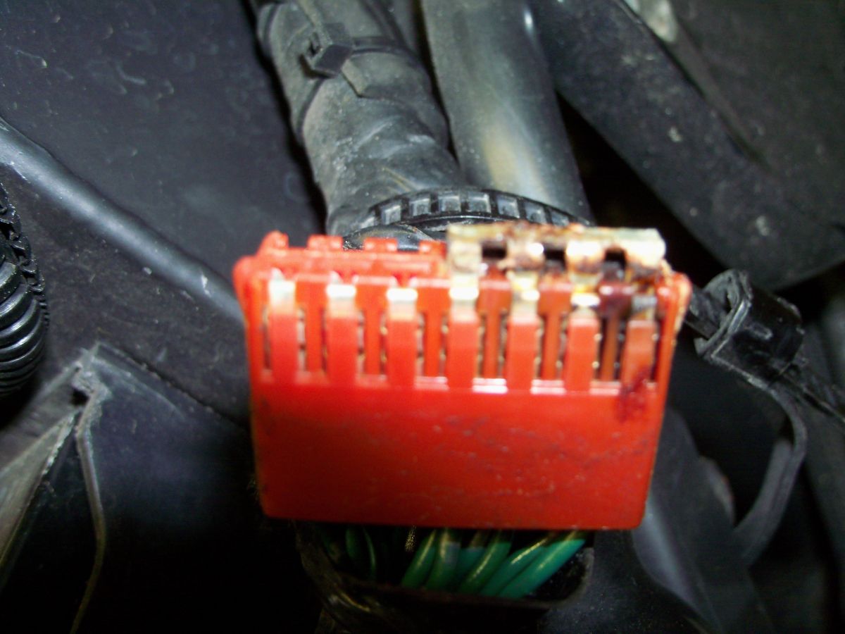
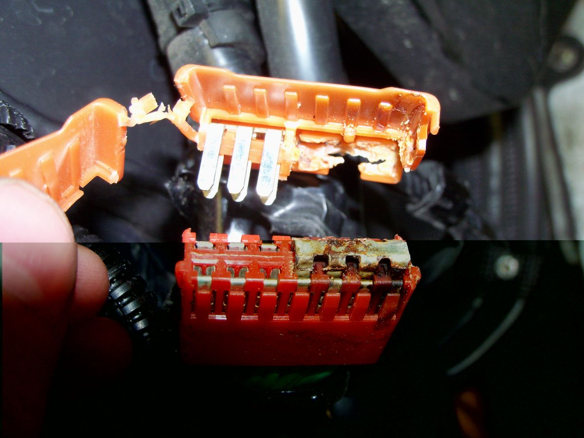
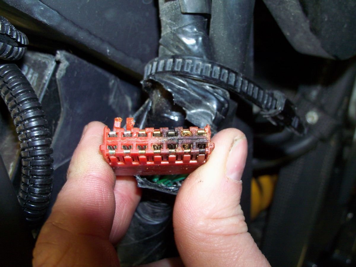
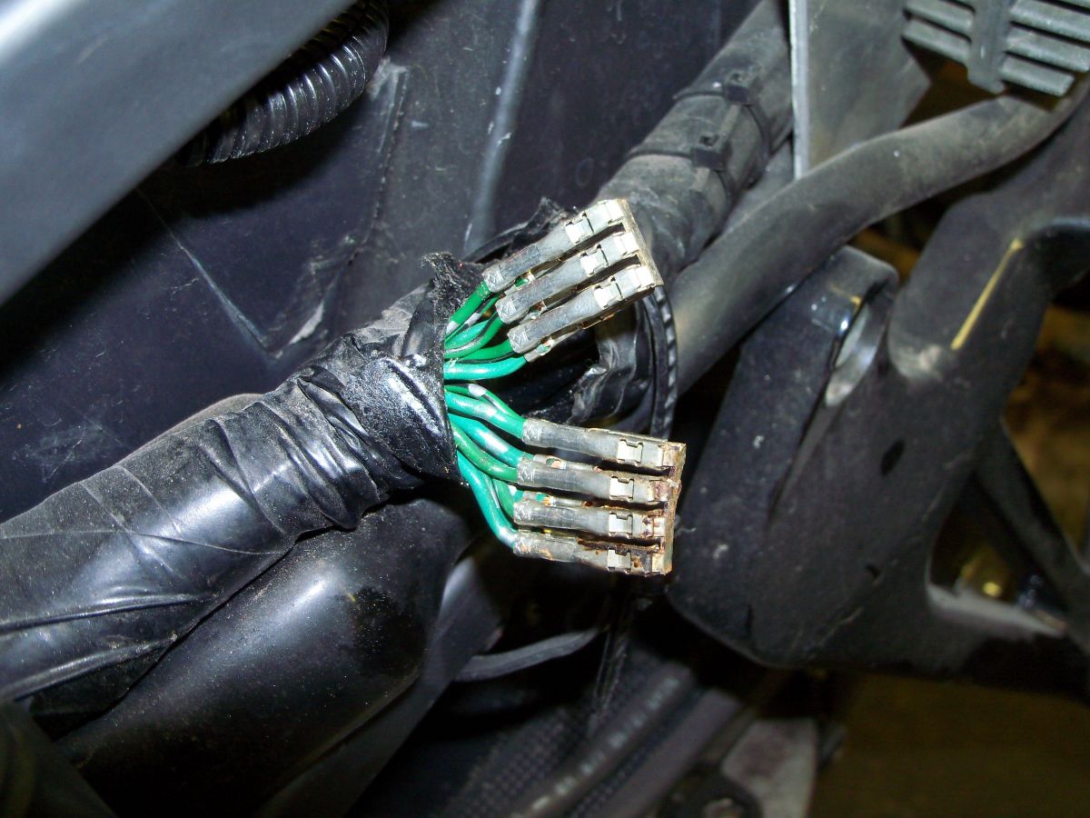
Fast forward to tonight and lookah hyar:

gallery_554_345_1719459.jpg

100 1097

gallery_554_345_1385261.jpg

100 1092

gallery_554_345_593842.jpg

100 1093

gallery_554_345_1119728.jpg

100 1094

gallery_554_345_369500.jpg

100 1095

gallery_554_345_988465.jpg

100 1096

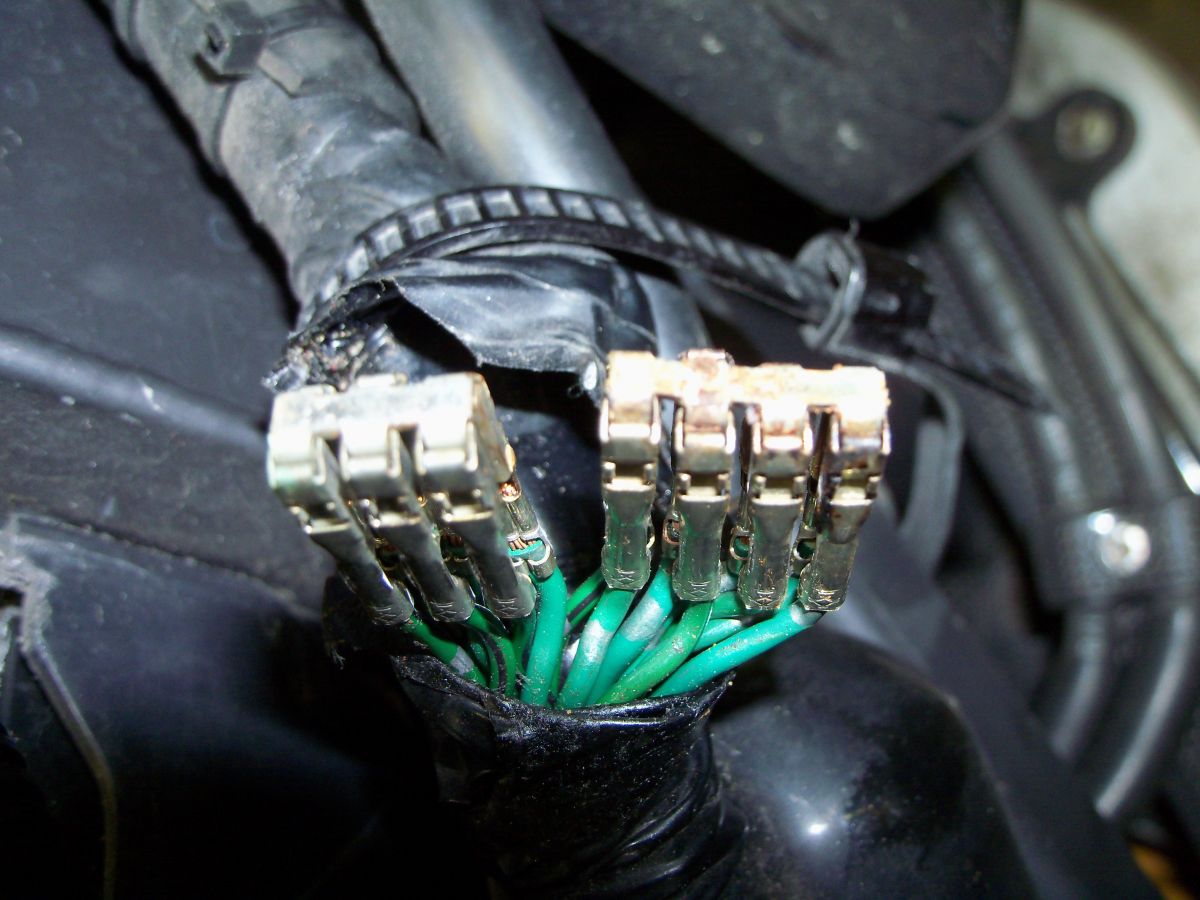
I didn't fix anything yet, just stuck them together with the common bus to keep them in order. Does anyone know why they are arranged in those groupings?

I mean, they are all grounds, but why separate them?

I'm thinking about tying them all together, soldering and routing straight to the batt just to give a better path to ground and not rely so much on the original path, in case there are other weak points.

I guess I should bring out the FSM and pore over the wiring diagram and see exactly which devices tie into this block, just for info's sake.

#2

Mate, well done. It doesn't take rocket appliances to see that your connector has had the richard!

[/Ricky trailer park boys]

:goofy:

#3

Wow, weird... I don't even recognize where or what that is... :huh:

#4
KPerham

Wow, weird... I don't even recognize where or what that is... :huh:

Orange grounding block, left of the battery, wrapped in the wiring harness.

I suggest you run, don't walk, and check yours before your next road trip is ruined. :fing02:

#5

its a block wrapped under a few layers of tape, and its a reason i always say.. GROUND YOUR BIKE IN AT LEAST 3 PLACES...

in this case.. just solider all of them together and wrap it up.. and add a few grounds straight to the frame. :fing02:

#6

Tightwad will be along shortly to fill us in :fing02:

#7
Veefer800Canuck
KPerham

Wow, weird... I don't even recognize where or what that is... :huh:

Orange grounding block, left of the battery, wrapped in the wiring harness.

I suggest you run, don't walk, and check yours before your next road trip is ruined. :fing02:

I ran my R/R negative direct to the frame, and the positive direct to the battery. I wonder if that would help in your situation?

#8
KPerham

I ran my R/R negative direct to the frame, and the positive direct to the battery. I wonder if that would help in your situation?

These grounds are for a bunch of little things, probably including the ECU, possibly the fuel cut relay, etc, which explains my running problems.

#9
The Phantom

Mate, well done. It doesn't take rocket appliances to see that your connector has had the richard!

[/Ricky trailer park boys]

:goofy:

Another trailer park boys fan, I LOVE IT!!!!

"We'll get two birds stoned at once"

"man he passed, he passed with flying carpets"

"What goes around, is all around"

"Im buying a real diamond, not one of those cubic zarcarbium pieces of crap"

My absolute favorite Rickyisms!!!

#10

And here I thought you were such a well-grounded individual Rob. :laughing6-hehe:

#11

Lucky it didn't start a fire !!!!!!!!!!!!!

#12

I know from cars that some things are controlled with - inputs rather than +.

Probably not the case here, but something to be mindful of while soldering them all together.

Can anyone confirm that this is not the case?

P.S.

My fav. episode:

Al sits on a couch across from a gay guy and says to him: You work, you clean, you cook, you like watching sports...... Mary me!

That was priceless.

My wife felt insecure ever since :laughing6-hehe:

#13
Veefer800Canuck

gallery_554_345_988465.jpg

100 1096

I didn't fix anything yet, just stuck them together with the common bus to keep them in order. Does anyone know why they are arranged in those groupings?

I mean, they are all grounds, but why separate them?

I'm thinking about tying them all together, soldering and routing straight to the batt just to give a better path to ground and not rely so much on the original path, in case there are other weak points.

I guess I should bring out the FSM and pore over the wiring diagram and see exactly which devices tie into this block, just for info's sake.

I don't think these ground wires are "arranged" for any specific reason, other than the grounds for numerous circuits are run to this ground connector. I think the thing to consider is that there are many individual circuits in the wiring of the bike, but not all have the same voltage or current requirements so some circuits are okay with a smaller connecting and ground wires. For instance, when looking at the wiring diagram, have you ever noticed that the positive side of some circuits are connected together, and the grounds of other circuits are also tied together before terminating at the final ground? On the other hand, you'll also notice that very high current circuits typically have their own dedicated positive and ground wires. That should make sense since it appears in the photo that some ground wires are of a heavier gauge than others. Either way, because the overall wiring consists of numerous circuits and several different harnesses that connect to each other to form a complete harness, then the only way to get "grounds to ground" is through connectors which over time corrode and fail. Also, even though all of these ground legs "see" the same ground, they "see" ground individually. That sorta matters when it comes to making sure a bad ground in one circuit doesn't create a ground feedback loop in another circuit.

I don't think you're really gaining anything by tying all of these grounds together and running a final lead to the negative terminal of the battery. As long as your negative battery cable is good and well grounded to the frame, then I think the best solution is to connect each of these grounds individually to a terminal strip, with the other side connected to central ground with a heavy gauge wires. Food for thought...

#14

I love this. Laughed out loud when reading it. :laughing6-hehe:

Sorry for the hijack. Al Bundy is truly one of the funniest characters.

He (Ed O'Neill) is equally funny on 'Modern Family'.

Also, on the electrical front. More areas to ground your wiring doesn't make it more grounded. One ground is all that is required.

Your house and all the wiring (high/low voltage) all goes to a single ground. Adding more wouldn't make a lick of difference.

Rice

P.S.

My fav. episode:

Al sits on a couch across from a gay guy and says to him: You work, you clean, you cook, you like watching sports...... Mary me!

#15
superfunkomatic

Also, on the electrical front. More areas to ground your wiring doesn't make it more grounded. One ground is all that is required.

Your house and all the wiring (high/low voltage) all goes to a single ground. Adding more wouldn't make a lick of difference.

Sort of. Your house is AC and Ground serves a different function. Although not recommended you can run your house without Ground, if you do keep the weenies and marshmallows handy. In a DC circuit ground is a vital pathway and a bad ground can have some very negative effects especially in a system with micro controllers. In DC the longer the ground the more interference and the greater likelihood of a ground fault. DC grounds are best when they are short(in length) and frequent.

#16

So when I find this connection on mine, I should probably take all 14 grounds, and add a 15th wire. Solder all 15 together and take lucky wire #15 and ground it to a freshly scuffed area on the chassis?

It seems like it is a good idea just to attach all of these grounds together, but is there going to be an advantage to taking that bunble and then adding an additional ground to the frame?

Jason

#17
blkcruzer

So when I find this connection on mine, I should probably take all 14 grounds, and add a 15th wire. Solder all 15 together and take lucky wire #15 and ground it to a freshly scuffed area on the chassis?

It seems like it is a good idea just to attach all of these grounds together, but is there going to be an advantage to taking that bunble and then adding an additional ground to the frame?

Jason

I don't know what the ground connector wiring looks like on a 5th Gen, but it doesn't matter since I seriously doubt you will be able to solder fifteen 14 gauge wires together. If your connector is toasted like the one in a photo in this thread, you'd be better off splicing in new individual wires ahead of the connector, and then running each new ground wire to the ground post. There is no advantage to combining them...

#18

Does anyone know why there is a connector there in the first place? Just for convenience maybe in changing out part of the loom?

Maybe the best solution is dispense with the connector and solder the apprpriate wires together, each to their own...

#19

Hmmm... that's one connector I haven't laid hands on yet. My VFRNess should be arriving soon, so I'll dig into that one when I go in for the 'ness.

#20

Each of the groups already has a wire going to ground somewhere on the bike, just solder the the wires in each group together, or connect to 2 connection blocks and the wiring will maintain it's integrity for whatever reason Honda did it this way. Probably as suggested previously to keep different current use devices apart. This is a common method in computer main frames and instrumentation and control systems. It helps stop spikes getting into sensitive devices via the back door i.e.through the Earth if commoned with thin wires.

Good idea to check the ultimate frame connections too and clean them to make good contact, tinned copper and aluminium don't mix too well in the long term.

The separation of these earth clumps is a bit of sophistication which Honda used but didn't carry through to their charging system, the fundamental basis of the VFR electrics. :pissed:

#21
Synaptic Misfire

DC grounds are best when they are short(in length) and frequent.

+1 to this. :fing02:

#22

So I figured out a solution. :cheerleader:

I have a spare, partially hacked up wiring harness, so I checked out the orange block.

It was in pristine condition, so I removed it by cutting it from the harness, carefully slid all the connectors out the backside, and will clean and tighten my connectors, slip them into the new/used orange block, douse the whole works in some electrical grease to prevent future corrosion, and put the OEM cap back on, also from the good used part.

#23

Sounds more like a temporary fix to me. :mellow:

#24
SEBSPEED

Sounds more like a temporary fix to me. :mellow:

That particular block outlasted most of the rest of his bike!

#25
y2kvfr

Hmmm... that's one connector I haven't laid hands on yet. My VFRNess should be arriving soon, so I'll dig into that one when I go in for the 'ness.

Is there a thread somewhere listing all the dodgy connectors and where they're located? These photos of charred plastic are beginning to make me nervous...

Glenn

#26

[image: View Post]SEBSPEED, on 24 April 2011 - 06:51 AM, said:

Sounds more like a temporary fix to me.   :mellow:

The OEM ground connector worked and lasted 11 years and over 70,000km with absolutely zero upkeep and maintenance.

I figure if I clean it up now and grease it, plus check it semi-regularly, it should do.
#27
You're late!!


BYC

OK so it's orange on the 5th gen... but I can now say "I warned yas allll y'all!!"

Don't bother trying to make that connector work, it is design impaired... FUSE THE LOT TOGETHER!!!!                    ...and using a soldering torch is fun!!

Maybe people will take note now and do the BYC/BOC mod, thing.
#28
So, after going for a ride yesterday, ashamedly, the first of the season, my damn FI lignt was flickering, and the bike shut down twice.   :pissed:

So even though the grounding block was borked, and I cleaned all connections and replaced the orange block with one from my spare parts harness, that still did not fix the problem.


Tearing into the FI and engine stop relays, I found the FI relay connection to be perfect, but the Engine stop relay connection looked like this:

[image: Posted Image]
IMG 0078

[image: Posted Image]
IMG 0079

I cleaned everthing up shiny and nice with sandpaper, tightened the female spade connectors, and swapped the two relays around, for no particular reason, they are identical.

I figured I had it licked, but no, it's still randomly flickering the FI light, except the bike never shut down on me.


Next is to disassemble and clean the sidestand safety switch, and the kill switch on the handlebar.

Can't be the main keyswitch, as I JUST put a new one on, and the problem is still there.


MAYBE one of the relays I took off today is slightly flakey inside, I guess I should take them off again and test them with a multimeter, following the service manual.

I had that happen with a 15A breaker in my house. Was randomly tripping with no faulty equipment or wiring. Changed the breaker, problem went away.
Dismantled the old breaker and sure enough, it was in poor condition, probably 30 years old.


Did I mention I HATE electrical problems?   :comp13:    :computer-noworky:
#29
Consider checking all of the wires coming out of the ECU.  I've read that even a small break in one of those wires will cause weird problems.
#30
Yeah, I did some googling and found a thread on VFRw about a 5th gen with a bad pink wire from the ECU that was causing grief. Will check that plus a few other things.....
#31

[image: View Post]Veefer800Canuck, on 23 June 2011 - 01:10 PM, said:

Yeah, I did some googling and found a thread on VFRw about a 5th gen with a bad pink wire from the ECU that was causing grief. Will check that plus a few other things.....

IIRC, the pink wire = speed sensor in Honda-land.
#32
OK, so I read the post by Snowdog, likely copied from the UKVFR site, which is great, the more info, the merrier!

http://www.vfrdiscus...post__p__786445


I also tore apart the spare parts harness I had lying around, and traced all the grounds from the main fusebox, starter relay, battery and R/R connections aft to the ECU and taillight/signal light plugs.


There are three ground wires coming from the ECU, 2 go to the main grounding bolt outboard of the RH framespar, somewhat near the brake proportioning valve and 1 goes into the cursed orange block. That same single wire also hooks into ALL the taillight/signal light grounds and hitches a ride en route to the orange block on one SKINNY LITTLE WIRE as there is a hidden splice under all the wrapping.

:mad: :mad: :mad: :mad: :mad: :mad:

Actually, there are a BUNCH of hidden splices all over the place which are crimped together and covered in blue tape, before being bundled an wrapped at the factory. Bad Honda, BAD!   :pissed:                             


I tore apart the orange block, despite the repair I had done earlier, in which I THOUGHT I'd solved the problem, it seems it still was there.

SO, I grouped the connectors together in bunches of 6 and 8,  like my earlier pic, with their original spade connectors hooked together and soldered each bunch to itself:
Posted Image

I wrapped the wires in wet paper towel so they would not fry as I needed a lot of heat to get the solder to flow through the groups of 6 and 8 terminals. Used a propane torch, on very, very low setting as my electric soldering iron would never have enough jam to do the job.


From each group of 6 and 8, I then soldered and ran a 14 gauge wire to the battery negative terminal and attached with a ring terminal for each.


THEN, from the ECU, I cut each of the three wires that went to ground, and soldered/shrinkwrapped a new 16 gauge wire to each of them, bundled them together in some split loom, and ran them along the LH subframe, crossed over in front of the battery, and put 3 ring terminals on the wires, and thence to the main grounding lug on the RH frame spar.

Started the bike up, no FI light, but that doesn't say much because it only came on intermittently before, and usually when using the tunsignals, or decelerating. Even then, it only flickered randomly, and never really stayed on steady for any amount of time, so only several good long rides will tell.


Frick, I hope this is the end of the problems, or else I might be looking into a whole new wiring harness. Hell, I've replaced EVERYTHING ELSE on the bike, that's about the only original part left! That, and the motor, LOL!!!!


I also ordered two NEW relays, fuel cut and engine stop (they are identical) off EBAY, for only $8.50 each plus ship. They are the exact same brand that Honda uses, same plug, same P/N, etc.

I figured for that price, if one of mine was weak, why not change them?

Oh, and I phoned my local Honda dealer to ask about the pricing on the two relays, and they quoted me like 38 and 52 bucks each, even though both relays are identical!!!   :comp13:

So no sale, sorry.
#33
One of the two new wires going from the defunct orange block right to the battery negative, the other one is nearby:

[image: Posted Image]
IMG 0080

3 new wires from the ECU to the main ground on the frame spar:

[image: Posted Image]
IMG 0081

You can only see two of the three wires coming out of the ECU here, tough to photo once it's all put together:

[image: Posted Image]
IMG 0083
#34
Good work Rob, hope that lasts you a while!
#35
Rode the bike about 35 miles in town today, absolutely zero flickering of the Fi light, and the bike never shut down in me.


Is it too early for a   :cheerleader: or a   :bliss: ???
#36

[image: View Post]Veefer800Canuck, on 19 April 2011 - 01:34 AM, said:

I'm thinking about tying them all together, soldering and routing straight to the batt just to give a better path to ground and not rely so much on the original path, in case there are other weak points.
Eh.
I did that, 'cept mine all looked hunky-n-dory. I ripped 'em all outta the orange thing, bunched 'em all togetherer, wrapped ''em up in some flat copper strip I have for reinforcing stained glass, and soldered the crap out of them. Oh - and I also added an extra wire to the bunch, and connected it to the frame.
#37

[image: View Post]Veefer800Canuck, on 19 April 2011 - 01:53 AM, said:

[image: View Post]KPerham, on 19 April 2011 - 01:45 AM, said:

Wow, weird... I don't even recognize where or what that is... :huh:


Orange grounding block, left of the battery, wrapped in the wiring harness.

I suggest you run, don't walk, and check yours before your next road trip is ruined.   :fing02:

Nice toast, er, post, Veefer, I'll be checking it soon.
#38
Quick update: no issues since the repair.

Fi light is quiet as a church mouse.
#39

[image: View Post]Veefer800Canuck, on 20 July 2011 - 02:34 PM, said:

Quick update: no issues since the repair.

Fi light is quiet as a church mouse.

You're my hero!   :blink:    :fing02:   

C
#40

[image: View Post]Veefer800Canuck, on 20 July 2011 - 02:34 PM, said:

Quick update: no issues since the repair.

Fi light is quiet as a church mouse.

I can say the same since doing the same (yellow) one on my VTEC... I reckon this connector has been well overlooked...
#41
Update: Bike has run fine ever since these mods were done. No Fi lights.
#42
Bump.
#43
- Still working out ok? -- I like to follow your stuff as my ride has lower miles than yours and I can see what may be in future woes...
#44

[image: View Post]Veefer800Canuck, on 24 June 2011 - 12:55 AM, said:


3 new wires from the ECU to the main ground on the frame spar:

[image: Posted Image]
IMG 0081

Rob, be SURE you have sanded ALL the paint/pc away from undwer this bolt of gound wires. It needs FULL contact with the frame for a positive ground!
Many vehicles have issues because of paint under ground points.

BR
#45
Yes Kevin, there is no paint under that connection. It was masked off before powdercoating.

I plugged all threaded holes in the frame with cheap hardware store metric bolts and flat washers, then lightly tightened them before it went in for powder coating, then removed all that hardware before installation, and used the OEM bolts where they belonged.
#46

[image: View Post]mello dude, on 25 April 2012 - 04:40 PM, said:

- Still working out ok? -- I like to follow your stuff as my ride has lower miles than yours and I can see what may be in future woes...

Electrical mods as shown in this thread are still working out fine. I recently put in a new stator (over the winter), not because it wasn't charging, I was still getting 14+ volts, but just because of time/mileage/peace of mind, I decided to bite the bullet and throw one in there.
#47
I should check this out on my now down Vtec, but I guess the new Main harness will take care of it.
#48

[image: View Post]Baileyrock, on 11 June 2012 - 06:36 PM, said:

I should check this out on my now down Vtec, but I guess the new Main harness will take care of it.

Like I said in the other thread (BYC Kentucky Fried Connector), you are better off dealing with this connector sooner than later... prevention is better than cure.

I have had zero electrical issues since doing this mod. Solid stator read outs and no blown tail lights... surging issues disappeared... you can only gain from performing this mod.
End of thread · 48 posts recovered Wayback Machine snapshot 23 Sep 2017