After reading thread upon thread, and fix upon fix, as well as doing my own R/R sensor wire fix, I have decided to pursue producing an after market wiring harness. I am tossing around a couple ideas, and could use some target audience input.
Currently the OEM harness, especially in 2002-2005 models has inherent problems. The possible solutions are:
#1. A new sub-harness that plugs directly into the existing R/R, and bypasses the OEM portion altogether. This would be a plug and play replacement with everything needed to just bolt in including a new 30 Amp fuse. Price would be approx $35 + shipping (edited to reflect current cost analysis)
#2. A piggyback version of #1. This would fit into the current harness, disabling the sensor wire from the ignition switch, and running new wires to supplement the OEM Ground and Rew/White wires. This would include everything needed to plug and play, and would come with a smaller fuse installed as it is a supplement, not a direct replacement. Price would be approx $45 + $7 shipping (edited to reflect current cost analysis)
#3. A combination of #1 and #2....you could decided whether to use the piggyback portion, or just the new section. This would have 1 extra connector pair, and would allow you to test the differences by disconnected either the OEM or New harness. Price would be approx $60 plus shipping. (Edited to reflect current cost analysis)
A pre 2002 version would be available as well, with similar pricing, but I would need access to a bike for fitting purposes.
First versions are rolling off the assembly line...errr....workbench as we speak. Harnesses available to cover 2000 and newer bikes. Price is $40 + $7 shipping($22 to Canada) and includes(possibly for a limited time only) a switched accessory wire at no additional cost!!
Please PM me for orders, and specify year of bike in PM.
*NEW*
I found an inexpensive fuse panel, which is compact enough to fit next to the rear brake master cylinder. I am offering this as a pre-wired kit along with my harness:
[image: Posted Image]
for $35 (plus shipping if ordered alone) I have everything wired for those getting the harness, just plug the connection together, you can also order it with just blank wires, for mounting without the VFRness. The fuse panel must be ordered with the VFRness for direct compatibility.
This includes 12 gauge wire to the battery with ring terminal, 14 gauge wire from accessory terminal on new VFRness to relay, 12 Gauge to ground from relay, input terminals commoned together to share the power lead, and 4 extra flag terminals to crimp your new accessories onto.
As with anything else, I solder all connections where at all possible.
If someone would like to purchase JUST the relay setup, add $7 for shipping, and the trigger lead will be 3' long, to reach any spot on the bike(taillight, etc).
added 9-13-07:
My website is now online, with most available options. I sell wire, connectors, terminals, tubing, and anything else VFR or Electrical related that I can. if you don't see it, just ask!
WWW.WireMyBike.COM
Update - 9-14-07
I have now received 2 calls from VFR owners who's sensor wire is hot all the time! Why this would be I am not sure, but it means the relay/accessory wire will also be hot all the time. This could potentially drain a battery. I would suggest checking the sensor wire voltage with the key off to be sure it is not energized before installing the VFRness. Should you find that it is, I will send a wire to replace the sensor wire, with a tap connection for connecting to a tail light or similar truly switched source(as the sensor wire SHOULD be).
Update - 9-19-07
Issue with non-switched sensor wire has been resolved, a different wire will be used for activating the relay and providing the R/R with the correct voltage reading. All VFRness's shipped from this point on will be the upgraded model. Those who need the upgrade will have it mailed to them.
For those wanting a clean start, I now have a great item to offer: [image: Posted Image]
From what I have seen on this and other boards, many of the problems are the same, but manifest themselves differently. Most seem to stem from wiring that isn't substantial enough, especially as it relys on other circuits as well.
On the 5th gens, maybe older ones as well, the Wiring is too small, so the wires cause resistance, which makes the R/R work harder, which makes the Stator work harder....the R/R working harder caused it to overheat. The stator working harder causes it to overheat as well. This is evident in the melted portions of harnesses and plugs. Changing the R/R fixes the issue for awhile, but then it wears itself out again.
My wiring harness will simply bypass(or suppliment) the OEM system, providing additional wires. In the "Beef up dem wires" thread, this was accomplished by cutting into the OEM harness and adding wires. Since many aren't comfortable with doing that, or don't know where to start, or don't want to jeopardize their warranty/risk hurting something, I am building a replacement harness.
If I can see an older bike, to measure the best route for the new harness(easiest to install, doesn't get in the way) I can build one for them. I have a 6th gen, so I am starting there.
I would be interested for a 5th gen, but would like more details as to what problems it is going to fix and would it be compatible with putting in a blue fuse box for future goodies.
This fix will cover the beefing up of the R/R wires(ground and charge) as well as fixing the 30 Amp fuse problem (distributes load through wires big enough to handle it). It will also fix the Monitor wire issue in the 6th Gen. It should solve problems associate with voltages not remaining steady and batteries being overcharged by the 6th gens(due to monitor wire giving incorrect reading).
There is no reason it won't work with the addition of a fuse box for future use.
Regarding the 30 amp fuse mod, I think there's some merit to beefing up the 30 amp fuse itself with a larger more robust 30 amp maxi fuse like the one in the link below. I've trolled thru all the electrical threads and I don't recall anyone mentioning this as contributing to the solution. When I described our problem to some electrical engineers where I work, they were in agreement about beefing up the wires/connectors but also suggested going to the 30 amp maxi fuse rather than the wimpy standard 30 amp.
You can find them at most auto parts stores, but would need a larger fuse holder.
I have ordered the items for the first test batch. I will make 3 kits to start. I have decided to go with option #2, which is a piggy back into the existing harness. Talus suggested this, and I like the idea of two systems working together which in the end gives greater strength. This option solves the "what do I do with the open plug" problem I envisioned as well.
The kit will come with:
2-20Amp fuses, one for the original 30Amp fuse holder, and one for the new fuse holder
1-Wire Harness to augment the existing setup, fully fused and relayed
1-set of directions with pictures to make it so simple my wife will be able to do it
The only tools needed for install will be:
fairing removal tools (allen wrench and small screwdriver for the plastic pins)
8 MM 1/4 drive socket/nutdriver on extension (wrench would work but might be harder)
10 MM Wrench/Socket
basic knowledge of anatomy (male/female difference)
A multi-meter would be helpful for testing the install, if you don't have one I can send one for $15 more that will do the job (I use it as a voltmeter on my bike)
I will have photographs as soon as my connectors, relays, wire, etc arrive. Basically the layout will be this(for those who are interested):
From the Positive terminal of the Battery, an 8 gauge wire(might be 10 gauge) into a fuse.
From the fuse, an 8 gauge wire will run to the R/R area (inside split loom tubing for heat/abrasive protection. The run will most likely be made under the tank, for ease of installation.
From here it junctions into 3 wires, 2 wires piggyback onto the existing Red w/White wires on the R/R plug. One wire goes to the Relay.
The two Green wires will have leads attached at the new connector, and will be joined by the relay ground on a terminal that will bolt onto/under the R/R
The existing sensor wire will be used to trigger the relay. This keeps the sensor wire keyed by the ignition switch.
The new sensor wire will run from the Relay, into the new connector.
If anyone wants to use JUST this wire harness, they simply use a 30 Amp fuse in the new harness, and remove the existing one from the original. I see no reason to want to do this, but the option is built into the design.
More to come, if anyone is a positive on it, speak up for first dibs. As soon as I get a 5th gen to see (and older too if wanted) I will be able to adapt to those years for correct design.
Took me about 5 hours to make, mostly because I was taking careful measurements, testing various options, and continually burning myself.
Every connection is Soldered, then taped/heat shrunk. I was forced to use some button-hole connections which aren't as pretty, but those too were soldered. All power wires are 12 Gauge, ground wires are 14 Gauge(will be 12 in the future, only had 14 gauge on hand for the first ones). The entire assembly is encased in split loom tubing (taped over) for heat.
More pictures will be coming, I am off to take my wife out on a date.
Remove Seat Remove Battery Remove 8mm bolts from front of tank, so it can be lifted up Remove Right fairing 2 Allen head bolts holding fairing to frame (they have a shoulder on them, so they are different visually when removed) 4 holding fairing to front fairing 2 holding fairing to black part behind the wheel 2 plastic retainers holding left and right fairings together(under fairings) - push in on center to remove (this was a HUGE revelation) 1 plastic retainer holding fairing inside wheel well - push in on center to remove (this was a HUGE revelation) Unplug connection from R/R to harness (5 wires in connection) Remove rear bolt from R/R (8mm head, use 1/4" socket on extension) Starting with the fuse end of the new Harness run it inside the frame where the radiator hose goes [image: Posted Image] next pull it up along the inside of the frame [image: Posted Image] then along the fuel lines that connect into the tank [image: Posted Image] From the left side of the bike: pull harness through to the front end of the battery compartment, here it is looking from left to right, under the tank: [image: Posted Image] feed harness behind battery compartment, and fuse out by the main fuses [image: Posted Image] This puts the battery connection next to the main battery connection [image: Posted Image] Next the right side has to be connected...this is simply a case of plugging in the new connectors, and bolting the ground loop under the R/R bolt. [image: Posted Image] The relay isn't going anywhere, but it can be zip tied to other wires to make it more secure. [image: Posted Image]
Replace the original 30 amp fuse with the supplied 15 amp fuse Put the right fairing on, bolt the tank back down, put the seat back on, and you are done.
I have finalized the price on the Harness system...I need a good name for it....I was able to lower the cost to $40 + $7 shipping for the US. Canada will be slightly higher shipping, whatever the added cost is.
For $47 you get:
1 wiring harness, ready to plug into your 2002 or newer VFR
1 Fused/relayed output wire, in a waterproof quick-connect, which will handle 15 Amps(based on fuse installed in Harness currently, wire/relay is rated to 30 Amp)....THIS IS NOW FREE!!!
1 set of instructions with pictures
Piece of mind that the sensor wire won't cause you problems, and that your 30amp fuse problems are also over.
Also available:
I also have Digital Volt meters. These can be had for an additional $8....I believe everyone should own one! Nothing fancy, simple Harbor Freight tool, but will save you a trip (I use one as a voltmeter on trips!)
PM me for payment details, products will begin shipping in 1 week.
This looks great, but one question.......What does the relay accomplish?
I can uinderstand a heavier wire and better connections so the RR see proper voltage to adjust to, but I'm confused on the relay.
The relay is there for two reasons:
#1. The OEM setup is switched via the ignition switch. I simply replicated that by using the sensor wire to trip the relay.
#2. The relay provides a handy point for adding a switched terminal for other accessories, without having to cut into the harness(and thus introduce more potential problems. This circuit will be fine with low demand devices, or will work well to trigger another relay for something like Heated Grips/Suits or a Video Camera that have higher draws, and should be on a dedicated line to the Battery.
This looks great, but one question.......What does the relay accomplish?
I can uinderstand a heavier wire and better connections so the RR see proper voltage to adjust to, but I'm confused on the relay.
The relay is there for two reasons:
#1. The OEM setup is switched via the ignition switch. I simply replicated that by using the sensor wire to trip the relay.
#2. The relay provides a handy point for adding a switched terminal for other accessories, without having to cut into the harness(and thus introduce more potential problems. This circuit will be fine with low demand devices, or will work well to trigger another relay for something like Heated Grips/Suits or a Video Camera that have higher draws, and should be on a dedicated line to the Battery.
Thanks........
On my bike (which is a 2004 ABS with 14K) I'm not experiencing any problems yet, except for high voltage. My radar detector gives me voltage read out and at times it's over 16.5V.
"The OEM setup is switched via the ignition switch. I simply replicated that by using the sensor wire to trip the relay" Why? Does this wire simply turn the RR on and off? If this black wire was "hot" all the time, would it be impossible to shut the bike off?
I've already installed a swiched aux fuse block, right in the general area of the RR. Can I simply hook up the black wire here? This fuse box turns on and off with the ignition, triggered from my tail light.
Well.....I decided to throw another option out for those who are interested.
I found a great 50 amp fuse panel(max for all branches), which just happens to fit under the seat on the 2002+ models...I am sure it would fit about anywhere on other models as well. Here is a picture of it:
[image: Posted Image]
And here are two mounting options (with and without relay):
[image: Posted Image][image: Posted Image]
I bought 3 of them, on a whim, but I can get more when I order more harness parts.
As far as cost....for those who are ordering the Harness, there shouldn't be much extra shipping, so just the price of the unit would need added. Without the harness, add $7 for shipping in the USA.
4-fuse panel - $15 8 Flag terminals(wires come out the side for tight fit) - $3.00, for $5(total) I will wire one side ganged together so all share an input Relay - $6 Wired Relay socket - $4 Relay and socket are only needed if you want a dedicated line to the battery. For those running my harness, the accessory wire will power them(or would power a relay). Max amperage suggested is 10 amps if power is obtained directly my harness, 15 amps is the max per line suggested by the manufacturer.
For those not running my harness, tapping into the taillight to switch the relay is a fairly easy option.
I do NOT have these yet(other than the 3 I ordered to see them), but if enough people want them(more than 5 or so) I will add them(and the relays and bits) to my next order. I will also post a seperate thread about them, but since I am offering to ship these with the harness(and because they fit in so well) I wanted to put them here. I have ordered them now.
Ok, the question has come up a couple times from those who already placed orders, and wanted to add the fuse panel, so I thought I would answer it here(my PM box is almost full):
For $35 additional to the harness(so $75 + shipping) I will include:
a wired relay(connected to the accessory wire on the harness)
fuse panel with inputs ganged together, and wired to the relay
12 gauge wire for connection to battery, with ring terminal
ground wire with ring terminal from relay
All you would need to do is hook the positive wire from your accessories to the flag terminal(included) then the flag terminal to the fuse panel, and install the fuse for it. You would ground your accessory wherever you liked.
I am going to order fuse panels and relays etc based on initial responce. To those who want to add this to their exisiting VFRness order, just let me know. There will be a slight shipping delay (4-5 days) as I will have to wait for these to arrive(other than the 2 extra I have now, which are spoken for already).
For those who are interested, here are the installation instructions for the VFRness. It also includes an explanation of why the problems exist, and how the VFRness helps.
Thank you for your purchase of the �VFRness��the ultimate fix for many of the charging system problems inherent to your VFR. This guide consists of 3 parts. The first part is an overview of the common charging system problems. The second is the history and construction of the VFRness. The third part is the installation instructions...made so easy even your significant other could install them.
Common Charging system problems:
The VFR is notorious for having a weak charging system. Honda many times has tried to compensate by making the Stator more powerful, adding cooling fins to the R/R, moving the R/R, and making the R/R self adjusting. Each �fix� brought with it new problems, and sometimes didn�t fix the old. The most common problem is�..HEAT. Heat is a killer for electrical systems, but it is rarely the problem by itself. Overheating is generally an indication that there is a problem SOMEWHERE ELSE. Typically heat occurs when the path the electricity is taking is too small for the current flowing.
Current paths and their impact:
The VFR has a couple weak links when it comes to current paths. One of them is the use of wires of too small a size. The second is switches/crimp connectors that build resistance over time. Both of these problems work together to cause many of the symptoms VFR owners are familiar with. Many riders are aware of the 30 amp fuse problem. That one is easy to see�.Red wire w/white stripe leading into the fuse holder starts getting brown and nasty looking, and loses its flexibility. Easy fix you say? Sure, replace the 14-16 gauge wire with 10-12 gauge wire. But did this fix it? NO, it doesn�t. It simply moves it. This 14-16 gauge wire is actually working as an indicator of the real problem�.wiring that isn�t big enough or connected well enough (and NOT the 30 amp fuse wire). Don�t get me wrong, when this wire turns brown/black, it needs to be replaced, but it isn�t the problem. Lets look at a hypothetical situation�.
Pretend you have a water source that can provide a large flow rate�AND has a booster pump to increase the pressure if needed. As long as you have the valve from this source open a moderate amount, and the hose is free of restrictions, you get a simple in and out process. Now pretend you kink the hose a bit. This reduces the flow of the water(and builds the pressure some). As the pressure builds, the hose flexes a little, but it is designed to handle some stress. But look at the water output? It simply isn�t big enough�.the solution�turn up the pressure�right? Ok, so we increase the pressure�water comes out of the hose faster, filling our bucket as we need�.but this increased pressure is stressing the hose even more, making the kink a bit tighter. The more water we try to get, and the more we increase the pressure, the worse the kink gets. The hose can handle the pressure, but the booster pump is having to work overtime to get the needed flow rate. In some cases the kinks may be so bad that even at max pressure flow is reduced to lower than what is needed.
This is what is happening with the wiring on your VFR�.�kinks� are forming�they don�t affect most systems, just those with the highest pressure demands. In our previous example, if we un-kink the hose, we could reduce the pressure needs on the pump, and the system would flow the needed water without stress. Un-kinking the wires is one thing the VFRness does. Simply un-kinking the 30 amp fuse may not be enough, we need to relieve the stress in other areas as well. This allows the full potential from the charging system to reach it�s goal, the battery.
The second weak link, which is restricted to the variable R/R units used from 2000 and on is the sensor wire. This wires one and only job is to read the battery voltage, and report it to the R/R. The R/R uses this input to decided how much juice to produce. Back to a water example�
We have a big plastic tank we are trying to keep topped up. The tank has various drains in it that may or may not be open, so we have a float-level indicator that lets us know when the tank is low�this triggers the booster pump to up the pressure and provide more water. But what if the float gets stuck or fills with water and reports a lower level that we have? Well, the booster pump ups the flow, and the tank gets filled�then overfilled�this is bad for the tank as it is only rated or designed to take so much pressure�and the booster can push well above this limit. Meanwhile the float keeps indicating the tank isn�t even full.
The sensor wire on the VFR gets �stuck�. It reads battery voltage alright..but through the ignition switch, which has a kink in it. Where it should be reading 13.5-14.5 volts, it only sees 11.5-12 volts. As a good worker it reports this number to the R/R(booster), and the R/R ups the power to try and fill the tank(battery)�.but the battery is full already. Overcharging the battery shortens the life tremendously. But when it goes bad, what is the answer? Replace the battery. The new battery seems to have solved the problems, but in reality it is just a cover for the real problem, which is bad wiring from the sensor wire to the battery. The R/R overcharging also pushes more power through the small wire on the 30 amp fuse, further making that symptom evident. On 2000+ models the VFRness fixes the sensor wire so it can report the correct voltage. This also appears to have been fix in the 2006+ model wiring harness.
History and Construction of the VFRness:
My background is heavily in autorepair, with hobbies in small electronics. I enjoy inventing, soldering, and being a geek. The VFRness came to life not because I had a problem(which I did and didn�t realize) but because I was seeing others have problems. I could see from the many questions asked in the topics dedicated to helping people resolve their Charging System problems that there were many who didn�t feel comfortable taking on these repairs themselves. In some cases they would do the bare minimum our of necessity, in others they had Honda replace their whole harness to fix the problem. Worst of all, some were replacing the symptomatic parts more than once, and never solving the real problem.
As I started looking at solutions, I figured I should look at the charging system on my bike, just to see. I connected my volt meter to the battery, and knew I had a problem�.15.8 volts at 5K rpm�this was almost 1.5 volts too high�and then it spiked to 16.1 when I turned the high beams on!!! I checked out my 30 amp fuse wire�.sure enough it was starting to turn colors and get stiff. I changed the wire, knowing this was a symptom not a cure, then a hunted for the real problem. When I connected my meter to the sensor wire, I got 11.8 volts�meanwhile the bike was running at 15.8 volts. I checked the wiring diagram to be sure there wasn�t something designed to make the reading low on purpose�.nothing. As a test I jumpered a wire from the positive terminal to the sensor wire�bingo, volts dropped to 14.35 and I had the answer.
As I was about to leave on a trip, I simply made that connection more permanent so it would last. I also relayed the connection so it wouldn�t be on when the bike wasn�t. As I rode the 650 miles to Albuquerque, NM, I thought about a solution. When I returned I had the key�I would find the connector Honda uses, and make an intermediate harness that would not replace the existing wires, but simply augment them. Most importantly, it would do it with no cutting, soldering, crimping or special tools needed. I didn�t need this wire myself, I am comfortable wiring button hook connections etc. but I knew I needed a design that would work for anyone.
The first VFRness probably took me 6 hours to make. Careful measuring, wire path design, and working with the OEM setup were all part of this. I also needed BIG wire�because the VFRness would never skimp. I used 8 gauge where 12 would do, 12 where 14 would do, and 14 where 18 would do. I crimped AND soldered every connection, and used battery terminal rings that were over-rated by about 10 times. I realized the one thing the original sensor wire COULD do correctly was trigger a relay, so I used it for that.
The final result was a harness nearly 4.5 feet long, designed to run from the R/R on the right-front of the bike, under the tank along the fuel lines, behind the battery to the fuse area, and back to the positive terminal for connection. The ground connection is designed to bolt to the R/R(short wires are better than long). Each VFRness is handmade and takes about 2 hours to construct.
Installation of the VFRness on 2002+ models:
Overview:
Installing the VFRness is as easy as it could be. You will need the following tools:
Allen wrench for body panels Small 8mm socket on extension(or a nutdriver) for the tank and the R/R bolt(just one) 10 mm socket or wrench for the battery Small piece of wood or similar to prop the tank up (or a loving someone to hold it)
The following items must be removed:
8 Allen head bolts and 3 panel clips to remove the body panel (there are 3 different bolts, keep them separate) 2 more clips on the battery cover 2 bolts on the battery(always start and end with the ground wire) 2 bolts at the front of the tank
Prepping the bike:
1. Remove the seat and set aside 2. Remove the battery cover by pulling on the 2 black plastic nubs and set aside 3. Remove the ground cable bolt(right side) from the battery using the 10mm socket. Watch to be sure the nut in the battery terminal doesn�t fall somewhere. Flex the negative cable aside, so it is out of the way. 4. Remove the positive cable bolt(watch the nut again) 5. Remove the rubber strap from the top of the battery and set aside 6. Remove the battery from the tray and set aside 7. Replace the 30 amp fuse in the main holder with the 15 amp version in the little bag supplied with your VFRness. 8. Remove the two 8mm bolts from the top of the tank, near the handlebars. Set these somewhere safe. 9. Remove the two trim clips under the fairing, and the 1 trim clip in the black panel behind the front wheel near the top of the panel. These are best removed by using a small screwdriver or key to push in the center about ��, then pull the trim clips out. Set these aside with the tank bolts. 10. Remove the 2 Allen head bolts from the top of the right fairing panel, remove the 4 from the side of the panel, and the 2 from the front (in the black part behind the front wheel). Note which length and style of bolt came from which hole. Two of them have a shoulder on them. Two others are slightly shorter(from the black part behind the wheel). The other 4 are the same, and connect the fairing to the top/from fairing. 11. Carefully pull the panel back and out from the bike. There is tab on the front fairing that catches the panel�slight pressure will disengage it. 12. Locate the R/R. It has fins, and is bolted above the radiator on the right side (under the panel we just removed). Remove the 8mm bolt at the back of the R/R�we will be putting a wire under here. 13. Follow the wires from the R/R to the plastic connector. This is usually located inside a clear rubber boot. 14. Push the rubber boot away from the connector, and disconnect the connector by push down on the locking tab while pulling them apart. 15. Lift the tank(it hinges at the back, neat huh?), and prop it with a small board, pole, etc.
Installing the VFRness:
1. Lay out the VFRness. Note the end with the connectors that look like the R/R connector. Check to be sure they match the connections on the bike. There is a male and a female connector, they only fit one way. 2. Starting with the fuse end of the VFRness, feed it along the top of the radiator hose to the inside of the frame of the bike. Reach down from the top, and pull the harness up along the frame until it is level with the top of the frame. 3. Following the thick fuel lines, route the harness towards the left side, and a little bit towards the back of the bike. 4. From the left side of the bike, continue pulling the harness until most of the length is out the left side. 5. The fuse end must end up with the other fuses, so routing it under the black subframe behind the battery is the best way. 6. Carefully thread the fuse end along bottom of the subframe until the fuse can come out the subframe near the other fuses. 7. Be sure the VFRness is rotated such that the positive connection, 10 inches from the fuse, comes out near the positive cable. It should reach out about 4.5 inches, enough to bolt to the battery but not have excess in the way. 8. Reinstall the battery in its tray, and test that the positive cables both reach the battery terminal. Go ahead and bolt it down now, main cable on the bottom, VFRness cable on top. 9. Reinstall the rubber strap, but do NOT install the negative cable at this time. 10. Once all lengths have been confirmed, and it fits, use the supplied zip ties to hold the VFRness to the fuel lines�.this keeps it from moving around and chafing. 11. Lower the tank, and reinstall the bolts. 12. On the right side of the bike, connect the R/R connectors to the VFRness connectors. 13. Reinstall the R/R bolt, with the ground loop under it and tighten. 14. Carefully tuck the Relay and wires against the frame. There isn�t a particular place they need to be, just close enough that they won�t interfere with the body panel. 15. Reinstall the negative cable(but not the battery cover yet)
Testing:
1. First test the battery voltage with the bike off. It should be 12.5-13.2. If it is lower, charge your battery before testing. 2. Disconnect the accessory plug, and test the voltage at the female terminal. It should match battery voltage. 3. Start the bike, and retest the voltage, you should have around 13.5-14.5 at idle. 4. Increase the RPM to 5,000 RPM, and test at 5,000 RPM. You should have 14.3-14.5 volts. 5. Retest the voltage at the female accessory terminal. It should match charging voltage now. 6. Try different RPMs and various lights on/off�.make sure the voltage doesn�t vary widely from 1500-5,000 RPM
Reinstall the battery cover, seat and Right fairing. The secret to installing the plastic clips is to take the center portion out, reinstall the body, then insert the center portion once again.
Assuming you made it this far, congratulation on the installation of your VFRness. You can now rest easier knowing that you have removed the kinks and false readings that have caused so many owners incredible grief and problems. If charging system problems remain please contact me for help.
I did more testing tonight on my own bike(small sample size, but the wife won't let me buy more for this...)
With a 15 amp fuse in each, I have no problems. I tried combinations of high beam and various RPMs. Upon removal of the 15 amp fuse in the OEM fuse holder, the other blew as soon as I started it. With a 30 amp in just my harness it was also ok. Rosscob, the only person to have installed one that I am aware of, has the fuse blowing problem.
I can't at this time say it is a problem, but I would suggest watching for it. Worst case you run a 30 amp in just my harness, and you remove the fuse from the OEM harness. Everything then functions as before, with my much improved fuse holder handling the whole load easily.
By no means do you want to use JUST the OEM wire after installing my harness on any 2000+ models. This will cause certain overcharging as the R/R reads the battery as completely drained, and does it's best to fill it.....at 16+ volts. Always fuse my harness!
Production is now continuing. I have changed to a purple wire on newer harnesses for the trigger wire to the R/R. This should keep any confusion away when it comes to crimping/soldering. I have made some changes to the Additional Fuse Panel as well, the only crimped connection there is on the flag terminals, which can't be both soldered and covered. They are however heat-shrunk to help avoid an issues.
I am also coming along on a website. This is slow as I am not good at that, but soon I will offer all my choices there. I may also speak with others who have items they produce for the VFR about putting them on a common page....this would make it easier for everyone to find I think.
I have never shipped anything to Spain before, so I will look into the costs of doing so.
As far as differences, here is what I have found:
1990?-1997 had a 6 wire plug, 3 yellow, 1 red, 1 green, 1 blank. This is different from the 6 wire plug of future Honda use. The bottom center portion is blanked out in the shape of a T, and helps center the plug(I imagine). Problems here are Temp and Insufficient wire size. Some didn't even have cooling fins! All are too small to spread the temp load. R/R is located on the RH Rear, under the tail.
1998-1999 had two plugs, a 4-wire and 3 wire. 4 Wire was 2 Red, 2 Green. 3 Wire is the yellow Stator wires. Biggest problems here are temp related, plus some with insufficient wire size. Also too small to spread the temp load. R/R is located LH Rear, under the tail.
2000-2001 has 6 wire and 3 wire plugs. 6 wire plug has 2 Red, 2 Green, 1 Black/white. 3 Wire is Stator Yellow. This is the same R/R as 2002+ models, but under the tail as with 1990-1999. Still heat associated problems, although not as bad. The Sensor wire is also an issue, and causes overcharging because it senses a voltage drop in the ignition switch. R/R still located RH Rear, under the tail.
2002-2007 has 6 wire and 3 wire plugs. 6 wire plug is the same as the 2000-2001 model, but the 3 wire plug is updated (not upgraded, still crap). R/R is located under the front right fairing. Cooling is no longer a problem, but the Sensor wire still is, as is general wire size not being suffecient. This is usually evident in the 30 amp fuse wire burning up and batteries dying prematurely.
The 2000-2001 models below are initial trial fits. Split Loom tubing is sent seperate for a more custom fit, along with 8 zip ties(instead of 4). All models include 2 20 amp fuses.
2000-2001 Model w/Fuse Panel option:
[image: Posted Image] 2000-2001 Model w/o Fuse Panel Option:
[image: Posted Image]
2002-2007 Model w/o Fuse Panel Option: [image: Posted Image] *note that the single wire connection is no longer included, as it was causing confusion and isn't very helpful
2002-2007 Model w/Fuse Panel Option:
[image: Posted Image]
10 sets will be shipping tomorrow, after which 6 sets remain until I begin taking orders again. Upon verification that the 2000-2001 models will work I will be selling 1998-1999 models. There will be no relayed accessory wire on 1999 and older models, but I will sell a kit for making your own relayed setup, including a Fuse Panel if desired.
I am looking into the amp/fuse question. so far one of the Electronic technicians that i work with seems to think that you could put two 30 amp fuses in and not have issues. Theoretically a 31amp spark would kill 1 fuse then kill the remaining fuse. The major issue is latency and how long the over amped condition is allowed to remain before both fuses blow to protect the system. I will try to test this on something tangible and less expensive than my bike. I think that a car amplifier should do the trick. Most car amplifiers have multiple fuses on their chassis but this is because there are multiple internal channels and discreet amplifiers inside of the housing. These chassis fuses make this an easy test without risking the amp. give me a couple of days and i will post back. now for some ear plugs...
2-20 amp fuses is my current recommendation. This should in no way overload the circuit. If this doesn't work, 30 amps in just my harness will also work.
I am interested in the results of your test, so please share.
I have updated the first post to clean it up a bit. I have also ordered the plugs to make 50 more 2000+ models.
I have worked with Ricks Motorsport Electrics for a fix for the 1990-1997 models. He has offered a great R/R that I can wire for a direct fit for these bikes! It has a larger size(I think) than stock, so it may require a relocation to work best.
As of this time, estimated cost is $120. This includes:
Brand new R/R
Wiring to battery and ground all soldered
Wiring/Connection for R/R to stator plug
1 year Warranty through me, back to Ricks.
This same R/R would theoretically work for any year, although personally I prefer the 2000+ models with the sensor wire (when they work correctly)
This message is going out to all 2003 VFRness purchasers:
I have been made aware of a wiring difference in the 2003 model bikes, but may extend farther. Apparently, in this year at least, the sensor wire is NOT a switched wire.
Q: How do I know know if mine is?
A: Test the accessory wire of your VFRness for power with the key off. If it has power, your sensor wire is live all the time.
Q: What does this mean?
A: This means your bike could have a power drain all the time from the relay and anything connected to it. This is counter-productive to what the VFRness was designed to do.
Q: Can it be fixed?
A: Yes, it is fixable. I am currently looking at different options. The best option is to replace the sensor input wire with a true switched source. Options for finding a switched source are being weighed currently. The tail-lights are a common source, and are easy to access, but aren't close to the VFRness. I prefer something closer if I can find it.
Q: When you find a fix, what will it cost to fix it?
A: It won't cost YOU anything. I promised a fix for the VFR problem, and if at all possible that is what I will deliver. I will be sending out a replacement wire, with instructions for installation as well. The only delay is in finding the best placement for the wire.
I would love to have other model years check theirs...so far no 2002 user has reported a live sensor wire.
According to the PDF manual, 2002-2007 are all switched. According to a 2003 manual, the wire is connected to the Red wires from the R/R. This was also seen in the harness Ken took apart, and I seem to recall some discussion then about why it didn't show in the wiring diagram.
What I am trying to determine is:
What years are wired live?
Is it ABS specific?
How can we know without testing everyones bike which way theirs is wired?
Why did BYU lose to Tulsa? (this one is not VFR related, but still important to me)
I had the opportunity tonight to have a 2002 non-ABS version in my Garage. We found that the sensor wire is non-switched...as it seems to be for all non-ABS. Maybe this is the deciding factor?
On the plus side, I also found a nice close switched wire....the ignition switch wires run right past the R/R plug. This means the tail-light won't be needed, just 6" of wire with a T-tap on it.
As a bit of a poll from my customer base....which would you prefer:
#1. Sensor wire from Harness to Relay has a disconnect spade terminal. Extra wire is included with a matching spade...if your sensor wire isn't switched then you disconnect the spade terminal, and tap into the ignition wire with the spare wire.
#2. Spare wire with Relay end, you remove the sensor wire terminal from the relay(using small screwdriver) and replace it with the terminal for the extra wire, and tap into the ignition switch wire with the T-tap.
#3. Leave the sensor wire out of it altogether, and just get that source for the relay from the ignition wire, using the aforementioned T-tap.
I should have the 1998-1999 model ironed out this weekend....The bike is coming up from Houston for the work!!!
For the 2003, the place to check is the black/white wire in the R/R harness. Test it for voltage with the key off. If you find no voltage, then it is switched.
I am considering changing all kits to eliminate that wire, and use the switched source from the ignition instead. This will keep it simpler on my end, and reduce the possibility of someone getting a harness that won't work correctly.
I will have a replacement R/R option by this weekend as well, fully wired to plug directly to the bike. It is a 40 amp R/R, so it will work with any VFR model from at least 1990 up.
I want to give a big thanks to those who have allowed me to play with their bikes thus far, it has been a pleasure to meet you, and also your bikes.
I just noticed last weekend that my tripometer & clock reset themselves. I may need this sooner than later. I'm gonna put a multimeter on to get some #'s, do I check the voltage at the battery terminals @ idle and at 5K. I'm a bit slow when it comes to lectric stuff.
I just noticed last weekend that my tripometer & clock reset themselves. I may need this sooner than later. I'm gonna put a multimeter on to get some #'s, do I check the voltage at the battery terminals @ idle and at 5K. I'm a bit slow when it comes to lectric stuff.
Yes, you want to check voltage at idle, 5K and with the brights on. Voltage should be fairly steady, not under 14 or over 15.2 or so.
I have finalized the fix, and updated the VFRness to cover those who's bikes don't have a switched wire. Incidentally, that seems to be anyone without ABS....that was the only common denominator I found among those who responded.
Here is the wire used: [image: Posted Image]
With the crimp connector in place:
[image: Posted Image]
The wire you tap is located here: [image: Posted Image] the wire is a Red w/black wire, in a 4 prong plug. It is located right next to the R/R plug, maybe 4 inches away at most.
Connector being crimped: [image: Posted Image]
Wire inserted into connector: [image: Posted Image]
Those who get the new harness won't need to remove the original wire from the VFRness, but for those who need to: [image: Posted Image]
you can see the wire goes into the left side, if you orient the power lead to the botttom and look at the relay plug from the back
Purple Output wire --->	___

 new wire goes here  --> |	  | <---Green to ground

   Power (Red)	  -->	 |
I do believe this could be the solution to so many R/R woes experienced by those with older bikes especially. This is a 40 amp R/R that is the same size as the 2000-20007 models. It does NOT have the monitor wire, for good or bad, and will work as a general replacement for models from at least 1990 and up...possibly all VFR's altogether.
It comes standard with 30" of wire, no connector. This leaves me plenty of options for using it as a stock replacement on and bike, or I can make it a custom fit if it needs relocated, and run the wires to the battery and grounds directly.
Here is a side comparison view:
[image: Posted Image]
The mounting holes are slotted, to work in a variety of locations. Dimensions are as follows:
4 3/8" long 3" wide 1 1/8" tall 3-4" on center mounting holes 30" of wire, 2 Red, 2 Green, 3 yellow
Cost bare is $110 Cost Wired for 2002-2007 is $120 Cost wired for 1998-1999 and older will depend on mounting location and plug options($120-$130 estimated). Cost wired for 1990-1997 will depend on mounting locations, no option for connecting to factory wiring($120-$130 estimated).
The same R/R sells from Dennis Kirk for $119, without plugs or custom fit.
I have finalized the fix, and updated the VFRness to cover those who's bikes don't have a switched wire. Incidentally, that seems to be anyone without ABS....that was the only common denominator I found among those who responded.
Here is the wire used: [image: Posted Image]
I hate to use this type of connector on any real elec. need, got something better? I've had this type Fail many many times! :goofy:
I have finalized the fix, and updated the VFRness to cover those who's bikes don't have a switched wire. Incidentally, that seems to be anyone without ABS....that was the only common denominator I found among those who responded.
Here is the wire used: [image: Posted Image]
I hate to use this type of connector on any real elec. need, got something better? I've had this type Fail many many times! :wheel:
As the current draw through the connection is minimal, I am comfortable with it. I would not use this to power anything with a current draw.
There are other options, but all involved more wires and more connectors. For instance you could use a 4-wire connector in the Ignition switch wire much like I used in the R/R harness, but this adds more possibilities of corrosion with more connectors(only 1 of the 4 would be needed).
I am open to any ideas on how to approach it differently.
Orders continue to come in, and shipments go out. I currently have 5 VFRnesses under construction.
This weekend I had the pleasure of designing a VFRness version for the 1998-1999 model bikes. In a 6 hour marathon session we managed to work around missing key issues (not the easiest part for sure), fit and finish the VFRness, Fit and Finish an accessory fuse holder, and Custom fit a brand new replacement R/R. Much thanks to amcnally336 who offered his bike as the test subject, and bore with me as I went through various iterations of fit options until we found the best version. The results were all we had hoped for(except we had hoped his R/R wouldn�t need replaced of course). I will post the actual numbers along with pictures in a little bit. VFRness will be available for order by Friday.
Lobster was also hard at work this weekend, taking my currently somewhat generic 2000-2001 kit and fuse panel, and making it a more perfect fit for those models. He provided tons of pictures, and will be offering change advise to me. I look forward to receiving that and passing along the installation tips he gives. Pictures from that also coming.
Last but not least, I have good news for the PowerletTM lovers out there�.I am now an Authorized PowerletTM dealer. I will be incorporating their product into various parts of my Harnesses where possible, to offer a wider variety of custom fit applications. If they make it, I can get it from them for you! I will be testing a couple of their options on my own bike to see how the fit and finish is.
Pictures of everything to come, I am hosting them on my website as I have used all of my VFRD bandwidth, and it is taking time to setup the Gallery there.
I know you said it was a moot point, but in the name of thoroughness and curiosity, I went ahead and tested the R/R's feedback lead on my 2003 European Non-ABS VFR. If I've done it correctly then it's definitely hot. Funnily, I noticed that the said B/W wire is really W/B (more white than black hehehe). Also strangely enough, this wire is not W/B over it's entire trajectory. The wire leaving the R/R up to the connector is solid black. Only once it leaves the connector and heads off to wherever it goes, is it actually white and black. This helped me decide which one to expect a live reading from, as the black one gave no reading. The W/B one did give a reading as you can see in the photos. Again, if I'm doing it right, it's definitely live.
The photos show the red "probe" from my multimeter, sticking onto the female slot of the connector correspondng to the W/B wire. What they don't show is me grounding the negative probe to various parts of the frame (just to be sure). Let me know if I'm doing something wrong, or if it's the wire between R/R and male half of the connector that should give a reading (doubt that for some reason).
I set the multimeter to Voltage D/C. As apparently that's one of the R/R's jobs, converting the A/C from the stator, to D/C which is valid for the battery.
[image: Posted Image] This is the connector here. There are three plastic hoodies with connectors inside. Under the plastic hoody for the R/R connector there was another connector. [image: Posted Image] Just so you can see the wire is black from R/R to male connector [image: Posted Image] Stubborn f&%$er to separate [image: Posted Image]
So good to hear you got to do the install and final design for the 98-99 model. How did the test run home for the generous owner go? Any feedback from him/her? Should I wait for Lobster's run-down before I order the whole kit and kaboodle (1 x VFRness + Fuse box and 1 x Blue-connector fix for my 03 and 1 x VFRness and 1 x Fuse box for my 98er).
Anything else I might need? I figure if you distrust crimping a wire to another, you could always buttonhole and solder, right? Might give more reliable results with the vibrations the V4 produces, not to mention potholes etc.
Lobsters fit covers the 2000-2001 models only. The 1998-1999 version is now complete! I also created a special harness for those who wish to use a 2000+ R/R on their 1998-1999 model bikes.
This includes the 3 wire plug and terminals to convert the Stator plug on the 2000+ models to the 1999 and older models. I will be adding this, and the regular 1998-1999 model, to my website hopefully this evening. I will also post more pictures of the normal 1998-1999 model.
I have 5 1997 and older plugs. They were outrageously expensive, and i am hoping for a better cost going forward. The other issue is that only the Harness side of the connector is available, as the other is built into the R/R, and has an odd layout (T-shaped blank spot in the middle of one row).
At this point the plan is to disregard the factory harness and go straight to the battery(through a fuse of course). I still need to verify the Stator wire length and connection.
Essentially it takes the stock charging system wires, and doubles(or more) the paths. It also provides a solid ground at the R/R unit.
Here are the readings from the 1998-1999 develoment/test subject
Initial: 13.00 at Idle 13.3 at 2500 13.51 at 5500 RPM
W/VFRness: 13.00 at idle 14.27 at 2500 13.90 at 5500
w/VFRness and new 40 amp R/R: 13.6 at Idle 14.6 at 2500 14.6 at 5500
As you can see, the real problem was the R/R unit, but the VFRness helped boost the charging system. It should also help prolong the life of the new R/R. The R/R initially installed was the upgraded Honda unit...and had only been in place for a short time.
I will be adding instructions for older models as I can. The 1998-1999 is very easy:
Remove Seat
Disconnect Rear Cowl
Disconnect battery - and + (in that order)
Disconnect R/R plug (LH side of the bike, next to the battery)
Remove front R/R bolt
Install VFRness into R/R plugs
Bolt ground wire under front R/R bolt
Position new fuse holder between original and main fuse panel
Connect + wire of VFRness to battery +
replace OEM 30 amp fuse with 20 amp supplied in kit
replace - cable
Test voltages for proper charging
reinstall rear cowl and seat
To keep this altogether, I quoted this from the Modifications area.
I'm not sure if I am one of the first to put the VFRness on a 2000 VFR, but Tightwad was looking for some fit / finish information for how the kit worked on the 2000/2001 models and I promised him I would take notes and post a quick how to. Overall, the product is well made and Tightwad was helpful in answering a few of my dumb questions.
I still need to ride around on the bike for a few hours with the new harness just to make sure all is OK (don't ask...work has been hellish) and I also want to check for the signal wire issue and check the charging voltages. I haven't had any R/R problems yet (knock on wood) so I don't expect any issues post install.
Sorry is a few of these steps are "duh" in nature...
Remove the seat. Remove the tail fairing (six allen bolts and four wire harnesses to the tail lights) Remove the battery box cover.
[image: Posted Image] IMG_0389.JPG
Disconnect the battery wires...watch the little nut on the bottom side of the connector!
The R/R is located on the left side of the bikle under the tail fairing. This should be pretty obvious once the fairing comes off.
[image: Posted Image] IMG_0388.JPG
Remove the two bolts holding the R/R in place. be sure to watch for the nut on the back to fall off, or be prepared with a long, twisty magnet to retrieve them when they fall...ask me how I know that one.
[image: Posted Image] IMG_0387.JPG
There are two wiring harnesses coming from the R/R. You only need to unplug one of them...the clearish colored one. Leave the white one connected.
[image: Posted Image] IMG_0390.JPG
I also took the time to gently push / prod the stock wiring harness as much out of the way as possible. You can see here I zip-tied the harness to the frame rail. Take a few minutes at this point to clean things up, wipe off dirt, and generally try to straighten up anything which looks "hangy" or loose.
[image: Posted Image] IMG_0392.JPG
Plug in the connectors of the VFRness...one goes into the factory plug, and the other goes toward the R/R. They will only fit one way. Now it's time to start thinking about where you want the extra wires to route. Honestly there isn't a lot of room to play with, and I recommend playing with a few options until you get something neat and tidy with no kinks in the wires. I guess you truly don't have to unbolt the R/R completely, but I think it helps to have that loose to play with wire route options. (The two loomed wires in the center are the new harness.)
Step 1
[image: Posted Image] IMG_0393.JPG
Step 2
[image: Posted Image] IMG_0394.JPG
Step 3
[image: Posted Image] IMG_0395.JPG
Tightwad recommends bolting the harness ground to the R/R itself...I'm sure to save some wire and some space. I double checked the ground there and it was present as long as I scraped a little paint off things to get a good contact (although the wire has a ground through the harness anyway...I also found). You could perhaps grind some paint from the sub frame and make a new ground if you like.
The "extra" 20 amp fuse has plenty of wire to be put somewhere you feel comfy with. I chose to put it more or less right next to the stock 30 amp fuse. (Don't forget to change the 30 amp fuse to the supplied 20 amp fuse.)
[image: Posted Image] IMG_0397.JPG
[image: Posted Image] IMG_0391.JPG
I also purchased the access plug panel, and with the Sargent Seat I had plenty of room to install it just aft of the battery box. Install is pretty easy...the purple wires connect the relays to each other...then just wire up pos and neg to the battery terminals.
[image: Posted Image] IMG_0399.JPG
Getting the extra wires onto the battery terminals using the stock screw took a little effort. I stuck a small pick under the nut on the terminal so it would be held up high enough to allow me to start the bolt and cinch everything up. I also had to trim a little of the battery box cover away to make it fit over the new VFRness wires.
[image: Posted Image] IMG_0396.JPG
Once you get that done, you're done. Check to make sure all the electrics work and the bike starts. Do the charging test (as recommended by Tightwad and many others here...) and then put everything back together.
I will update this post with my charging test results and the sensor wire fix (if necessary) as soon as I get a chance.
If I missed something, or you have questions, please chime in.
ELECTROSPORT HAS PULLED ALL THEIR 3 GENERATION R/R's FROM THE SHELVES!!!!!!!!!!!!
THEY HAVE BEEN SELLING DEFECTIVE UNITS IT SOUNDS LIKE FOR SOME TIME.
I CALLED LAST WEEK I WENT THROUGH THE SAME CRAP WITH THE TECH SUPPORT THAT I DID BEFORE. DIODE TEST SAID BAD BAD R/R. THE TECH SAID HE WOULD CROSS SHIP ME A NEW ONE BUT EITHER HE WASN'T TOLD THEY WERE PULLING THEM OR WAS JUST TRYING TO GET ME TO GO AWAY!!!!!!!!!!!! YAH I AM GOING AWAY TO THEIER COMPETITOR. THEY WANT TO GIVE ME A CREDIT UNTIL THE NEW ONES COME
WANTED TO THROW THIS IN HERE FOR THOSE THAT MAY BE TRYING TO DIAGNOSE ISSUES. YAHHHHHHHHH ITS THEIR RR THAT IS NOT WORKING,
I have been going through this post and have not found anything about third generations???? They have 5 wires - 3-Yellow 1-Red 1-Green no black. As you can see from my FYI post from above I have been fighting the wrong fight and now have to start over again.
Question 1: Is there a harness being looked at for 3rd generation???? Ricks Electric has the connectors.
I was hoping to build a harness that would relocate the R/R somewhere else but have not decided just where yet.
Question 2: Does anyone have a recommendation for another R/R other than Ricks?? Anyone bought from www.regulatorrectifier.com
I have been going through this post and have not found anything about third generations???? They have 5 wires - 3-Yellow 1-Red 1-Green no black. As you can see from my FYI post from above I have been fighting the wrong fight and now have to start over again.
Question 1: Is there a harness being looked at for 3rd generation???? Ricks Electric has the connectors. I was hoping to build a harness that would relocate the R/R somewhere else but have not decided just where yet.
Question 2: Does anyone have a recommendation for another R/R other than Ricks?? Anyone bought from www.regulatorrectifier.com
While I responded to you in email, I thought it would be helpful for others who may have the same questions to see them answered, as best I know.
The extra Red and Green wire are just redundancy....I like Redundancy.
I feel the OEM design is inherently a weak link, and that an upgraded OEM model will just be an upgraded weak link. If I had a 3rd-4th gen, I would find a way to install a better R/R design. There is enough room there for changing it, and the wiring would have to be changed as well, but it would be worth the effort.
As far as a VFRness for the 3rd-4th gens, the problem is really that the R/R has the plug molded into it, and no replacements are to be had.
FWIW, I recently a sold a '92 w/20K miles on it and what appeared to be the original R/R and it put out a solid 14.7v across the board, way better than my '98 did stock, or even with the upgraded unit.
OK folks, this is my first post. I have a 96' VFR750 with 27k on it and what appears to be a bad regulator rectifier. The local shop here in prescott wants 241.00 to order it. I have been all over trying to find the best deal .... so what manufacturer is the best Electrosport, Honda, or Shindegen ... best price? Help! This issue is enough to make me drink again.
OK folks, this is my first post. I have a 96' VFR750 with 27k on it and what appears to be a bad regulator rectifier. The local shop here in prescott wants 241.00 to order it. I have been all over trying to find the best deal .... so what manufacturer is the best Electrosport, Honda, or Shindegen ... best price? Help! This issue is enough to make me drink again.
Thanks in advance very much!
While this is much too late to help I am sure, Ricks offers an R/R for the 750, and I can sell them for $115.
OK folks, this is my first post. I have a 96' VFR750 with 27k on it and what appears to be a bad regulator rectifier. The local shop here in prescott wants 241.00 to order it. I have been all over trying to find the best deal .... so what manufacturer is the best Electrosport, Honda, or Shindegen ... best price? Help! This issue is enough to make me drink again.
Thanks in advance very much!
grab it if its a oem, before you install it check all your electrics out as i truly belive the r/r is getting a bad rap for other systems causing the r/r to go south before its time.
I finally got around to installing Tightwad's VFRness on my '98. Wow! What an amazing difference. I went through the recommended test routine, and the readings are exactly as Tightwad said they would be. I have never seen these readings before. Thanks, Tightwad. And for those of you who haven't taken advantage of this modification, do it. Couldn't be easier. :goofy:
Another satisfied customer here. The R/R on my 99 was dying and Tightwad walked me through the diagnosis. Ordered a new R/R and harness from him, he shipped promptly, and then answered my questions on the install.
I can't say thanks enough for all the help. If you even THINK you might need/want an upgrade/replacement, check with Tightwad first! :biggrin:
Another satisfied customer here. The R/R on my 99 was dying and Tightwad walked me through the diagnosis. Ordered a new R/R and harness from him, he shipped promptly, and then answered my questions on the install.
I can't say thanks enough for all the help. If you even THINK you might need/want an upgrade/replacement, check with Tightwad first! :biggrin:
Seriously +1 to this! I ordered the VFRness and his fuse panel about a week ago. I haven't had any issues with the R/R, but I know it's a problem area...I had seen the posts about adding a wire here and there, and I have technical ability to do it myself...but with all the kind words Tightwad has received over this was enough for me to just pay him for the harness....and it was worth every penny....in time saved and eased of installation. I had a couple of questions and Tightwad emailed me right back with concise easy to follow answers.... if (fingers crossed) my R/R ever goes...I know I will be going to Tightwad for the new one.
+1 on the satisfied customer.
Kudo's Tightwad.
Very impressed with the quality of the wiring harness, looks like factory wiring(only better).
Same charging improvent as reported by others...solid 14.1v-14.3v from 2200 to 7500 RPM's with high beams + flashers on.
Before the VFRness...14v at idle...13.3 at 7000 RPM's with low beams only.
After reading thread upon thread, and fix upon fix, as well as doing my own R/R sensor wire fix, I have decided to pursue producing an after market wiring harness. I am tossing around a couple ideas, and could use some target audience input.
Tightwad,
I hope you get f'ing rich off this stuff.
Over the years I've replaced 2 wiring harnesses, every sensor, two batteries, two stators, I don't know how many RR's, etc, etc, etc, before spending the short money on this thing. Not an issue since. I probably dropped a couple grand fixing Honda's crap electrics before I came across this thing.
Suddenly, after 4 years of dicking around with this thing between breakdowns while i put miles on an FJR I shouldn't have needed to buy, at 90K miles the VFR has regained reliable status.
If we ever meet, I'll probably need to give you a hug, and want to kiss a little bit or something. :blink:
After reading thread upon thread, and fix upon fix, as well as doing my own R/R sensor wire fix, I have decided to pursue producing an after market wiring harness. I am tossing around a couple ideas, and could use some target audience input.
Tightwad,
I hope you get f'ing rich off this stuff.
Over the years I've replaced 2 wiring harnesses, every sensor, two batteries, two stators, I don't know how many RR's, etc, etc, etc, before spending the short money on this thing. Not an issue since. I probably dropped a couple grand fixing Honda's crap electrics before I came across this thing.
Suddenly, after 4 years of dicking around with this thing between breakdowns while i put miles on an FJR I shouldn't have needed to buy, at 90K miles the VFR has regained reliable status.
If we ever meet, I'll probably need to give you a hug, and want to kiss a little bit or something. :blink:
I would be happy just shaking your hand I believe....cash donations also accepted :huh:
I am glad to have helped, I find pleasure in it, even if it won't make me rich.
Just joined vfrd and found this thread,what a bonus.
This is my second vfr750fv, which I bought 2 weeks ago, last owner replaced the battery and r/r, but after stripping the bike to go through end to end, as I do when I buy a new bike, I found the plug to the r/r has a burnt terminal, on removal from the unit, I can see some burning to the terminal, only very light, question is, will I have to replace this, or can I clean up the pin.
I have in the past, on my own bikes and my son's removed the connector which joins the alternator to the loom and to the r/r and hard wired it.
The fv(97) has 5 wires 3 yellow 1 red 1 green.
I do like the idea of the loom ( plug and play)type.
Just joined vfrd and found this thread,what a bonus.
This is my second vfr750fv, which I bought 2 weeks ago, last owner replaced the battery and r/r, but after stripping the bike to go through end to end, as I do when I buy a new bike, I found the plug to the r/r has a burnt terminal, on removal from the unit, I can see some burning to the terminal, only very light, question is, will I have to replace this, or can I clean up the pin. I have in the past, on my own bikes and my son's removed the connector which joins the alternator to the loom and to the r/r and hard wired it. The fv(97) has 5 wires 3 yellow 1 red 1 green. I do like the idea of the loom ( plug and play)type.
Once the connectors burn, they don't seem to be the same. Hopefully you caught it soon enough!
do you do a loom to fit the 750 fv version, as I might as well replace the wiring whilst I have the bike in bits.
kev
The VFRness for the 750 is different from the rest in that it doesn't T into the charging circuit, but actually replaces a good bit of it...see the thread linked in my signature for more details, and you can find it on my website of course....but better data and pictures are compiled here on this great site.
hi kev,seasons greetings,just to but in i had burnt connectors etc on my fv wiring ,i used tight wads upgrade it sorted the problem out and am getting solid reading on my volt meter,20,000 miles + since rewire .i now carry out a wirig visual insp as part of my servicing regime.cheers rob. :schla15: hope this helps.
thanks for the reply, I can't quite grasp what happens to the wiring from the starter relay area, have you replaced the red/white wire with a red wire and put an inline fuse in there,the earth directly to the battery, stator wires just replaced with heavy gauge wire and new connectors,( I hard wired my son's cbr to eliminate the faulty/loose terminals at the stator plug.)
I have another problem with the bike I have just bought, it appears to have been a cat D, which has been bodged back together, the wiring from the ignition switch to the loom has been altered, it should have a 3 pin arrangement, but has a 5 pin plug which has been altered, do you know where I can buy the 3 pin plug, male and female, so that I can repair the wiring correctly, I will also have to replace the ignition switch.
The 3rd and 4th gen VFR has a 5 pin plug, with 3 smaller stator connections and the larger power and ground connections below them. If the R/R doesn't have this connection, then someone has spliced an R/R from a different model in.
The wires from the R/R plug go about 24" to another connection, where the stator wires come to from the stator.
I may have mislead you here, the connector to the r/r has indeed 5 wires. 3 yellow (stator) 1 green (earth) and 1 red/white, I fully understand the replacement of the yellow wires, with heavy gauge than standard and the relocating the earth to the battery, but why the replacement of the red/white wire and the inclusion of an extra fuse?.
It's the ignition switch wires that have been messed with, it should have a 3 pin connector, someone has fit a 6 pin connector (90-93) models, then cut out the two brown wires and left the other space empty, my question in regard to the ignition switch, was do you have access to 3 pin connectors that could be used for the rewiring of the ignition switch.
I may have mislead you here, the connector to the r/r has indeed 5 wires. 3 yellow (stator) 1 green (earth) and 1 red/white, I fully understand the replacement of the yellow wires, with heavy gauge than standard and the relocating the earth to the battery, but why the replacement of the red/white wire and the inclusion of an extra fuse?.
It's the ignition switch wires that have been messed with, it should have a 3 pin connector, someone has fit a 6 pin connector (90-93) models, then cut out the two brown wires and left the other space empty, my question in regard to the ignition switch, was do you have access to 3 pin connectors that could be used for the rewiring of the ignition switch.
many thanks
kev
The entire charging system on the 90-97 models essentially runs through the 14 gauge wire in the starter relay. This leads to burned up starter relay connections when the connection gets less than ideal...it happens so often my kit includes the Starter Relay Connector repair kit I also sell seperately.
I duplicated the path to the battery, with a second fuse. This 10 gauge wire leads to much more stable charging, and no more melting down the starter relay connection.
No connections are made to the ignition switch...just the Red/White wire in the starter relay.
I thought I had seen a diagram of circuit on one of these threads or your web site but I can not find it again, so you replace the red/white wire with a heavy gauge wire to handle better the amps, produced by the r/r.
I thought I had seen a diagram of circuit on one of these threads or your web site but I can not find it again, so you replace the red/white wire with a heavy gauge wire to handle better the amps, produced by the r/r.
regards
kev
There was a diagram of the 2002+ model, but it works under a different premise slightly. Essentially you have it correct, there is a 10 gauge wire from the R/R that goes to an inline heavy duty fuse holder. The is a wire that Y's off the 10 gauge that goes to the Starter Relay, where the original Red/White wire was. The other portion goes directly to the battery.
hi guys, off the subject quickly, i installed the vfrness on my 86, the collected grounds were bolted on the frame(wouldnt reach the battery) along with an additional ground from the battery neg.I read a steady 14.8 at idle and @5K .is that cool? or ...
I responded via PM...but for those who also want to know:
I screwed up and made both ends female on the purple wire. Could be my inner female lovingness manifesting itself? could be too many late nights? Either way that one was my fault...sorry about that!
There are no unused R/R or stator connections when installing the VFRness. It fits inbetween the existing R/R (not stator) connectors. This provides a duplicate path back to the battery, instead of an alternate path as many other options do...which inherently have the same issue the VFR does over time.
One of my issues with the install was how to fit all that mass of heavier guage wires and the connectors under the fairing on the right side. It seemed like I had to bend the wires almost into knots to get it under the plastic and then it still was a force fit. I'm sure I did something wrong. A couple of months ago I removed the VFRness to troubleshoot an electrical problem. I'm condisering reinstalling it , but not looking forward to craming it all under the plastic again. Any suggestions?
I responded via PM...but for those who also want to know:
I screwed up and made both ends female on the purple wire. Could be my inner female lovingness manifesting itself? could be too many late nights? Either way that one was my fault...sorry about that!
There are no unused R/R or stator connections when installing the VFRness. It fits inbetween the existing R/R (not stator) connectors. This provides a duplicate path back to the battery, instead of an alternate path as many other options do...which inherently have the same issue the VFR does over time.
That explains why I had no high beams, or front signal lights. Remember I had the HID kit so I had low beams . The previous owner had straight wired the stator and R/R.
P.S. I fix the purple wire wasn't a big deal but did not want you to make hundred of the wrong ones !!!
One of my issues with the install was how to fit all that mass of heavier guage wires and the connectors under the fairing on the right side. It seemed like I had to bend the wires almost into knots to get it under the plastic and then it still was a force fit. I'm sure I did something wrong. A couple of months ago I removed the VFRness to troubleshoot an electrical problem. I'm condisering reinstalling it , but not looking forward to craming it all under the plastic again. Any suggestions?
With the recall there are now more wires/connectors in that area than there were originally...thus it is a tighter fit. with a bit of forethought everything still fits however.
Maybe I should get the recall done so I can look at changes...but then I have to take it in!
I responded via PM...but for those who also want to know:
I screwed up and made both ends female on the purple wire. Could be my inner female lovingness manifesting itself? could be too many late nights? Either way that one was my fault...sorry about that!
There are no unused R/R or stator connections when installing the VFRness. It fits inbetween the existing R/R (not stator) connectors. This provides a duplicate path back to the battery, instead of an alternate path as many other options do...which inherently have the same issue the VFR does over time.
That explains why I had no high beams, or front signal lights. Remember I had the HID kit so I had low beams . The previous owner had straight wired the stator and R/R.
P.S. I fix the purple wire wasn't a big deal but did not want you to make hundred of the wrong ones !!!
Straight wiring the Stator to the R/R won't impact the VFRness, but the R/R being hardwired to the rest of the harness would of course. Feel free to call/email me if you still have questions
I had a deja vu moment when I started reading this post, then I remembered why. Two years ago, before I even had a bike, I stumbled upon it when I was searching for info on doing a Big Three upgrade while installing a stereo in my car (Batt (-) to frame, Alt to Batt(+), Frame to engine block). I ended up doing one on our other vehicle too, just because it makes sense. Reading this felt like being a witness to history in the making, like going back in time and watching the VFRness evolve. That sounds majorly corny, but I don't know how else to say it. Thanks for your hard work in making this awesome plug and play charging system upgrade for our bikes. You've got my business! :fing02:
Just finished my vfrness install and the blue connector fix on my 2003 abs model my initial problem was stator/rectifier connection block was melted (only 1wire thankfully ) installing it couldn't be simpler and tested as per instructions and all voltages in order i also used the stator repair kit and tested the stator for resistance and shorts to earth as per instruction on the wiremybike website and all perfect so it looks like i caught the problem in time.
however i have 2 concerns
1. My rectifier heats up very quickly and very hot to touch like its being overworked even at idle i know its supposed to heat up hense the cooling fins and its position being moved from the back of the previous model to the front but its REALLY HOT 😳 wondering if its on the way out because of the initial problem
2. Has fitting the harness DEFINITELY put an end to my woes or do i need to do other grounding fixes like the yellow block in the front sub-harness (soldering 13 earths together ) im going to visually check it anyway but if its visually ok then I'd rather leave it be
Just finished my vfrness install and the blue connector fix on my 2003 abs model my initial problem was stator/rectifier connection block was melted (only 1wire thankfully ) installing it couldn't be simpler and tested as per instructions and all voltages in order i also used the stator repair kit and tested the stator for resistance and shorts to earth as per instruction on the wiremybike website and all perfect so it looks like i caught the problem in time.
however i have 2 concerns
1. My rectifier heats up very quickly and very hot to touch like its being overworked even at idle i know its supposed to heat up hense the cooling fins and its position being moved from the back of the previous model to the front but its REALLY HOT wondering if its on the way out because of the initial problem
2. Has fitting the harness DEFINITELY put an end to my woes or do i need to do other grounding fixes like the yellow block in the front sub-harness (soldering 13 earths together ) im going to visually check it anyway but if its visually ok then I'd rather leave it be
New updates on the VFRness front:Orders continue to come in, and shipments go out. I currently have 5 VFRnesses under construction.This weekend I had the pleasure of designing a VFRness version for the 1998-1999 model bikes. In a 6 hour marathon session we managed to work around missing key issues (not the easiest part for sure), fit and finish the VFRness, Fit and Finish an accessory fuse holder, and Custom fit a brand new replacement R/R. Much thanks to amcnally336 who offered his bike as the test subject, and bore with me as I went through various iterations of fit options until we found the best version. The results were all we had hoped for(except we had hoped his R/R wouldn’t need replaced of course). I will post the actual numbers along with pictures in a little bit. VFRness will be available for order by Friday.Lobster was also hard at work this weekend, taking my currently somewhat generic 2000-2001 kit and fuse panel, and making it a more perfect fit for those models. He provided tons of pictures, and will be offering change advise to me. I look forward to receiving that and passing along the installation tips he gives. Pictures from that also coming.Last but not least, I have good news for the PowerletTM lovers out there….I am now an Authorized PowerletTM dealer. I will be incorporating their product into various parts of my Harnesses where possible, to offer a wider variety of custom fit applications. If they make it, I can get it from them for you! I will be testing a couple of their options on my own bike to see how the fit and finish is.Pictures of everything to come, I am hosting them on my website as I have used all of my VFRD bandwidth, and it is taking time to setup the Gallery there.
Just finished my vfrness install and the blue connector fix on my 2003 abs model my initial problem was stator/rectifier connection block was melted (only 1wire thankfully ) installing it couldn't be simpler and tested as per instructions and all voltages in order i also used the stator repair kit and tested the stator for resistance and shorts to earth as per instruction on the wiremybike website and all perfect so it looks like i caught the problem in time.
however i have 2 concerns
1. My rectifier heats up very quickly and very hot to touch like its being overworked even at idle i know its supposed to heat up hense the cooling fins and its position being moved from the back of the previous model to the front but its REALLY HOT wondering if its on the way out because of the initial problem
2. Has fitting the harness DEFINITELY put an end to my woes or do i need to do other grounding fixes like the yellow block in the front sub-harness (soldering 13 earths together ) im going to visually check it anyway but if its visually ok then I'd rather leave it be
End of thread · 81 posts recoveredWayback Machine snapshot 19 Oct 2015
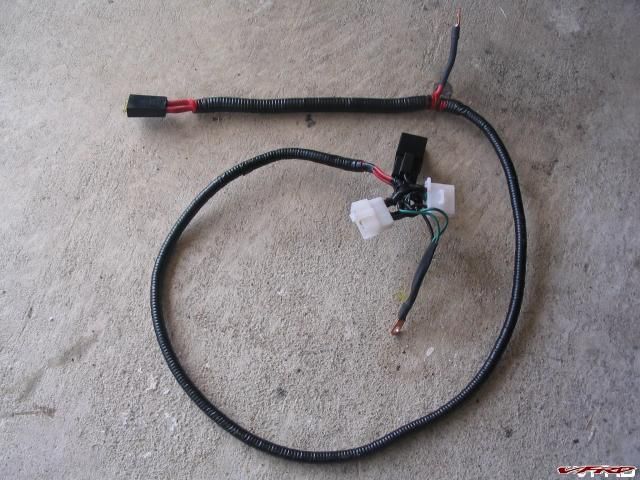
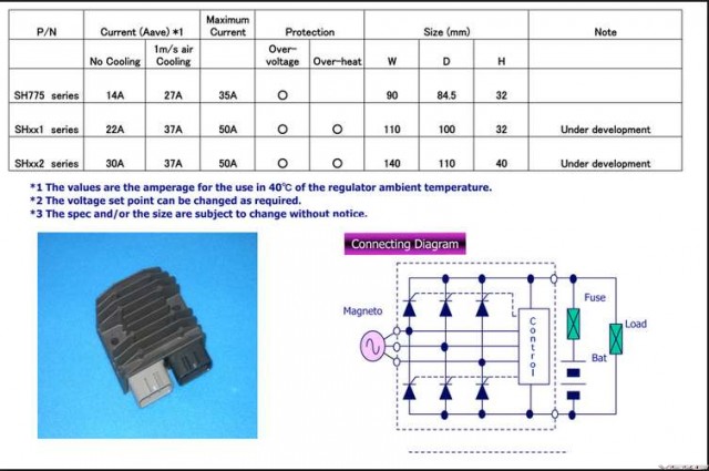
![[image: Posted Image]](http://images116.fotki.com/v717/photos/3/36012/4293098/DSC_0006-vi.jpg)
![[image: Posted Image]](http://img233.imageshack.us/img233/2781/24092007my3.jpg)
![[image: Posted Image]](http://img227.imageshack.us/img227/9766/24092007003kz8.jpg)
![[image: Posted Image]](http://img227.imageshack.us/img227/1694/24092007001uo3.jpg)
![[image: Posted Image]](http://img220.imageshack.us/img220/7219/24092007004go8.jpg)
![[image: Posted Image]](http://img220.imageshack.us/img220/2598/24092007005xr9.jpg)
![[image: Posted Image]](http://img101.imageshack.us/img101/3223/early5th6thgenconversiomq4.jpg)