VFRDiscussion ARCHIVE / READ-ONLYREAD-ONLY

5th Gen Engine Modifications

161 posts Started 7 Feb 2010 Last recovered post 29 Nov 2017 Wayback Machine snapshot 19 Jan 2022

#1
A couple of weeks ago a lister posed an interesting idea:  What could be done to an engine?

I posted in that thread but received much feedback asking to start a new thread.  So, here it is.

I myself am smack dab in the middle of such an engine project. About 3 years ago my brother dropped of an XT500 single cyl 4 stroke engine off at an engine dude's shop in Cali. They went round and round on the best app for the motor and finally came to the conclusion that bigger is not always better. My brother had the elusive big BIG bore kit and all the trimmings. The builder advised him against it as the torque was sooo much that it would twist the engine right out of its mounts. Instead they settled on a bunch of efficiency mods including Porsche tappits, Carrillo rod/Wisco piston, port/polish, and then he welded the head. In all the mods will produce 77hp up from OEM of 53.

So enough with that story. But listening to him describe his experience got me thinking. What would an efficiency job produce out of a 5th gen motor? So I was able to snag a very low miliage motor from a wreck and drop it off to him.

In my initial conversation with him we kicked some ideas around, all of them centering on efficiency/rotational weight and such. I told him all ideas were in play including Carrillo/JE combos, crank work, and anything that would reduce the weight and send the efficiency out the back. He said he'd take a look and let me know the best course of action.

During this conversation I discovered he worked in Europe during the late 80's as a builder/tuner on race RC30's. He also worked for MegaCycle Cams and then went on to tell me about the horror stories of the early Honda V4 cams he would have to fix. He confirmed what has been discussed here on VFRD about Honda's problems with those cams wearing out. He fixed too many to count, but knew that their failure was due to poor mfg/materials, not as much oiling.

Well, I'm about to jump out of my shorts after he revealed that info and I felt much better about the upcoming process.

About 4 weeks ago we spoke again and he handed me some mixed news. As far as my big plan to swap pistons/rods and work the crank, not so fast. He said that Honda already did all that work for us and that he could install the new bits, but for the money, no one would even notice the difference between stock and aftermarket. Boy was I surprised to hear that. I was expecting a "yeah, I did that and here it is." He said Honda built it very well.

He described the motor as running very rich as there was quite a bit of carbon build up. He also said that 1 of the 4 cams was already hosed. No other parts showed any wear. He chalked the wear up to a bad part(he took pics so when I get them, you'll all get them). All the other cams were perfect. He did say that the motor did not have many miles on it which is what I know to be about 3-4k miles.

So, he is headlong into porting/polishing and yes, welding the head shut increasing the compression. He may coat the cams for longevity. He commented that Honda loves to F up the ports by angling them off center which makes for a less efficient exit and a bit more difficult to port.  No big deal to do, just an observation.  He understand why they do it that way but knows it is not the best for efficiency.

I've told him about the PC V. He is very interested in the PC V and how it can maximize performance.

We talked about the oil pump and he said it was fine, but he did make an intersting remark about the cooler. He said that the cooler is installed upside down. Since it is not under great pressure and the oil flows into it from the bottom, the top row(s) are useless. He said that most mfg'rs do this and he does not know why. So I looked at my 86 project and that cooler feeds from the top, but subsequent gens feed from the bottom.

I have the complete plumbing from a 6th gen ready for mod onto this motor and I will invert the cooler so that the oil feeds from the top, drops down and uses all of the rows. He thought this to be a good improvement and actually uses the cooler for what it was designed to do.

Well, more as I get it along with pics. I expect the motor to be finished within the next month or two and then I'll have it shipped back to me. By then I should have all of the installation questions for the PC V worked out and oil cooler mod completed.

Yes, pictures as I get them.
#2
Thanks for the write-up, sounds like this guy really knows what he's doing with the motor.
Looking forward to hearing about the results!   :fing02:
#3
This is a great topic and I look forward to it's development so i am Pinning it.   :fing02:

Thanks and good luck.

BR

ps  get some pics in here before I have to Ban you!  http://www.vfrdiscussion.com/forum/public/style_emoticons/default/wink.gif
#4

[image: View Post]BaileyRock, on 07 February 2010 - 02:28 PM, said:

ps  get some pics in here before I have to Ban you!  http://www.vfrdiscussion.com/forum/public/style_emoticons/default/wink.gif

Nothing like a bit of peer pressure....

Here is the donor.  Nothing special except it is a 49 state'r and is pretty clean.  Might have a pilot assisted touch down on the clutch side but nothing that can't be worked.


Engine Builder Dude (EBD) installed a Factory Pro Shift Star EVO kit on Wednesday.  He had a bunch of comments about OEM shift linkage (all crappy) but agreed that this kit is a great addition.  

While he was there, he took a look at the water pump.  Once opened, he saw he could improve it by moving the impellors closer together, thus being more efficient and able to push more water through the system.  He's also going to inspect the complete plumbing system to see if any other improvements can be made (ie with 2 side mount rads, series v. parallel).

More as I get it.
#5
So am I correct in believing that simply flipping the oil cooler over will up its function and help keep the engine a few ticks cooler? Anything I can do to keep that motor turning for a bajillion more miles   :fing02:

I've always wanted to go through a 5th gen motor the way you are! so sweet!!
#6

[image: View Post]sa1713, on 07 February 2010 - 04:04 PM, said:

While he was there, he took a look at the water pump. Once opened, he saw he could improve it by moving the impellors closer together, thus being more efficient and able to push more water through the system. He's also going to inspect the complete plumbing system to see if any other improvements can be made (ie with 2 side mount rads, series v. parallel).
I have one of these:

http://www.daviescra...05-details.aspx

[image: Posted Image]


An electric waterpump means the mech drive is no longer required, and saves some power (it all adds up). Also you can set it up to run on when you switch the motor off, which eliminates heat soak.

When funds permit I'll get the digital controller for it:

[image: Posted Image]

Not cheap, but neither are engine mods, or repair of engine failure... I definitely plan to get more power out of my engine at some point, this is the first step towards that.

Good luck with the project, I'm looking forward to following it!
#7

[image: View Post]2fast2young, on 11 February 2010 - 01:42 AM, said:

So am I correct in believing that simply flipping the oil cooler over will up its function and help keep the engine a few ticks cooler? Anything I can do to keep that motor turning for a bajillion more miles   :goofy:

I've always wanted to go through a 5th gen motor the way you are! so sweet!!

Installing a 6th gen cooler will add an extra row of capacity!   :fing02:
#8

[image: View Post]BaileyRock, on 11 February 2010 - 10:38 AM, said:

[image: View Post]2fast2young, on 11 February 2010 - 01:42 AM, said:

So am I correct in believing that simply flipping the oil cooler over will up its function and help keep the engine a few ticks cooler? Anything I can do to keep that motor turning for a bajillion more miles   :goofy:

I've always wanted to go through a 5th gen motor the way you are! so sweet!!

Installing a 6th gen cooler will add an extra row of capacity!   :fing02:

And, in the conventional position, an extra row for oil to sit & collect in? :goofy:
#9

[image: View Post]SEBSPEED, on 11 February 2010 - 10:45 AM, said:

[image: View Post]BaileyRock, on 11 February 2010 - 10:38 AM, said:

Installing a 6th gen cooler will add an extra row of capacity!   :fing02:

And, in the conventional position, an extra row for oil to sit & collect in? :beer:

HAHAHAHA Seb, sometimes you just pull the words right from me.

Bailey, thanks for the tip, seriously, I didn't know they upgraded the coolers on the Vtecs.

But is getting more cooling out of the cooler simply a matter of flipping it 180 degrees?
#10

[image: View Post]The Phantom, on 11 February 2010 - 10:14 AM, said:

[image: Posted Image]
An electric waterpump means the mech drive is no longer required, and saves some power (it all adds up). Also you can set it up to run on when you switch the motor off, which eliminates heat soak.
Saves power? Doesn't that power get absorbed by the motor yet again driving the stator to power the electric water pump? I could see if that microcontroller turned it off and on by demand?
#11


[image: Posted Image]
An electric waterpump means the mech drive is no longer required, and saves some power (it all adds up). Also you can set it up to run on when you switch the motor off, which eliminates heat soak.

Saves power? Doesn't that power get absorbed by the motor yet again driving the stator to power the electric water pump? I could see if that microcontroller turned it off and on by demand?

Kinda; the stator generates power all the time whether it's used or not. If not used, it gets dumped as heat by the Regulator. If your stator is powerful enough to run an electric water pump, I'd imagine it's doing nothing more than helping avoid generating waste heat.

In short, I'm pretty sure the mechanical effort to turn the stator doesn't increase with the power being asked of it. The energy drain from the electric water pump at idle would probably be the biggest problem. Possibly the voltage could drop so low that the bike stalled. Oddly enough, switching off the pump here would be a bad thing because sitting at the lights on a hot day is when you really really need your water pump to be cranking!

Interesting video on electric pumps here:

http://www.youtube.com/watch?v=EZKA0Ef21z4
#12
Yep the digital controller will not only turn it on and off, but will run it at the appropriate speed for the cooling requirements at the time.

The stator is not going to add any real resistance to the rotating force of the crank. But pull your waterpump out and spin it by hand, there's resistance - then think about it having to push x volume of water through itself and around the engine at y rpm, the output shaft that drives it has to work pretty hard. It's also spinning madly when you're belting along at a brisk pace, which is when it should be backing off and letting the radiator do the work instead - the EWP (with controller) fixes that problem too.

Not cheap, but there's no cheap power increases on a VFR http://www.vfrdiscus...tyle_emoticons/default/smile.gif
#13

Yep the digital controller will not only turn it on and off, but will run it at the appropriate speed for the cooling requirements at the time.

The stator is not going to add any real resistance to the rotating force of the crank. But pull your waterpump out and spin it by hand, there's resistance - then think about it having to push x volume of water through itself and around the engine at y rpm, the output shaft that drives it has to work pretty hard. It's also spinning madly when you're belting along at a brisk pace, which is when it should be backing off and letting the radiator do the work instead - the EWP (with controller) fixes that problem too.

Not cheap, but there's no cheap power increases on a VFR http://www.vfrdiscus...tyle_emoticons/default/smile.gif


Actually, the increased need for electric current to run the electric water pump WILL add resistance to the rotor/stator. Think of an gas powered generator that you might used if your power goes out. If you plug in a big appliance, it puts a noticeable load on the engine. There's no free power. So lets say that electric water pump is a 1hp electric motor, then it will take 1hp (plus probably ~10% efficiency loss) extra power to spin the rotor to make the current for it. I think the advantage to these electric water pumps is the consistency. The mechanical pump in the engine gets really inefficient and sucks a lot of power away from the engine at higher RPM.
#14
I'm liking the discussion fellas. I could be totally wrong on this, but comparing the electric water pump's power usage on the VFR to a generator is not similar, as there is a battery involved. The stator is just there to replenish the battery, which is powering everything, whereas a generator simply makes electricity directly. I don't know what the generator does with the surplus energy (earthed?) but I'm pretty sure it's a slightly different system. Therefore there shouldn't be a noticable load on the stator, just the battery.

Kaldek raises an important issue about sitting at the lights idling when you need the pump working its best. Hence once fitted you may need to vary the idle in order to meet the pumps drain on the battery and ensure the stator is up to the task without having to adjust too high an idle rpm. Does the pump give any specs to power usage?

I think if the pump runs at a set rpm all the time you could set it up fairly easily, depending if the stator is up to the job of keeping the battery at a nice level. Phantom, why would you want the pump to switch off? Radiators work at higher speeds, but if coolant isn't flowing it seems odd to want to shut it off. Also, is it possible to control the engine rpms (with the controller) if the pump has variable speeds? (like aircon)
#15

Actually, the increased need for electric current to run the electric water pump WILL add resistance to the rotor/stator. Think of an gas powered generator that you might used if your power goes out. If you plug in a big appliance, it puts a noticeable load on the engine. There's no free power. So lets say that electric water pump is a 1hp electric motor, then it will take 1hp (plus probably ~10% efficiency loss) extra power to spin the rotor to make the current for it. I think the advantage to these electric water pumps is the consistency. The mechanical pump in the engine gets really inefficient and sucks a lot of power away from the engine at higher RPM.


But you missed the part where Kaldek mentioned that the Stator is putting out full juice all of the time, and the excess juice is bled to atmosphere as heat by the stator depending on whether the battery is satisfied or not.

Ever perform a stator voltage test with a voltmeter, disconnecting the stator from the R/R and checking the voltage on all 3 legs? It's full juice all the time if the stator is good.

What is it, 470-500watts or so? And 50 some volts? (fishing from memory here)
#16
1:21 to 1:35 Of the video they mention that the electric pump that they had designed for the Prius produces about 2% fuel efficiency compared to mechanical one.

I see several pros and cons here.

Pros:
- about 2% more mileage/power
- works only when needed - may help top end

Cons:
- $$$
- Packaging
- weight???
- potential point of failure as it may not be as reliable as mechanical one.
#17

Kaldek raises an important issue about sitting at the lights idling when you need the pump working its best. Hence once fitted you may need to vary the idle in order to meet the pumps drain on the battery and ensure the stator is up to the task without having to adjust too high an idle rpm. Does the pump give any specs to power usage?


No you don't need to change the idle, the drain is negligible.

Operating voltage is 4v DC to 14.5v DC. Max current draw is 7.5amps.

The digital controller pulls a few amps too (up to 12 max) but it also controls the radiator fan and can switch it on and off as required, as well as switch the waterpump on/off and vary the speed.

http://www.daviescra...05-details.aspx

I've used my pump on my VT Berlina (3.8litre V6) while I waited for a replacement waterpump - the kit comes with adaptors for a few different hose sizes and I just had to buy a few generic bits of radiator hose to make it work - and while the EWP115 would probably be a better long term bet from an efficiency point of view, the little EWP80 kept it at normal operating temps, and this was at the start of a Queensland summer.

VFRD member Vfroem is running an electric pump on his 140+hp big bore 3rd Gen, seems to be having no problems with it. His is a Mercedes pump, don't know what vehicle though.


I think if the pump runs at a set rpm all the time you could set it up fairly easily, depending if the stator is up to the job of keeping the battery at a nice level. Phantom, why would you want the pump to switch off? Radiators work at higher speeds, but if coolant isn't flowing it seems odd to want to shut it off. Also, is it possible to control the engine rpms (with the controller) if the pump has variable speeds? (like aircon)


Not switch it off altogether - just slow it down so it's performing at max efficiency. The OEM waterpump is hurling the water around inside the block at the fastest rate just when it's not (generally) necessary).

The pump runs at its max speed without a controller; not the ideal option of course, but fine if you were running at the track or had a motor that tended to run hot. I have the thermal switch that will turn it on and off to maintain a set temperature, but as mentioned when I feel ready to part with $200 (ouch) I plan to buy the digital controller which will just vary the impellor speed as required.

With the digital controller, you throw away the thermostat, and the controller varies the voltage to maintain optimum flow and therefore temp, the radiator fan is also on call when needed. I had planned to fit twin 5" R6 fans that I bought, but their combined weight is a bit more than the OEM fan and I don't need that extra efficiency with this pump.

Speaking of weight - Rice, the pump weighs 900g and the digital controller weighs 90g... I suspect that the OEM waterpump might actually weigh less than this, will try to weigh it (if I can find it...)

To answer your other points - it's the same size as the OEM pump and fits perfectly in the OEM location; I am thinking of putting it above the stator cover though, so I can ditch that heavy metal waterpipe that runs down below the stator cover. Will have to see if there's room once my bodywork is done. They seem to be pretty reliable and the latest version has a "SiC x carbon mechanical face seal for added reliability". I'm guessing that 50000km is possible especially given that it will be off or running at low rpms a lot of the time, and on a little 750 it won't need to work nearly as hard as on a bigger motor - its designed to be able to cool engines of up to 5 litres so it will be understressed on the VFR. Except at the track http://www.vfrdiscus...tyle_emoticons/default/smile.gif Davies-Craig has been supplying thermofans and other products to the Australian (and o/s) auto industry for 40 years, their quality is excellent.

Cost, well there's not much you can do about that. It's top shelf quality and low volume production. Again, VFR power doesn't come cheap, and unless you go big bore or blown, your only option is a series of small mods that will add up to more power and if you're lucky less weight. For me - EWP, cam scissor gears removed (makes it horribly noisy though), full headers, EGR system modded to reduce crankcase pressure, K&N - so far. Head and cam work is planned. I'm hoping for 115-120hp and faster throttle response, to go with my 20kg or so weight reduction.

This tangent is getting pretty big for Sa1713's engine mod topic :goofy: Might leave it at that, I'll post some pics when the final installation happens on my bike.
#18
I like it!
Was skeptical at first (as always) but I like it now.
It is definitely a better way of cooling the motor.
Someone with a Torocharger may want to consider this setup as well methinks.

Phantom,
Since you are determined to go the distance with the power theme, it may be a good idea to keep records of fuel mileage and possibly even dino results (if funds allow) before each mod.
I would be very interested to know how much HP does mechanical pump require to turn.
#19

I'm liking the discussion fellas. I could be totally wrong on this, but comparing the electric water pump's power usage on the VFR to a generator is not similar, as there is a battery involved. The stator is just there to replenish the battery, which is powering everything, whereas a generator simply makes electricity directly. I don't know what the generator does with the surplus energy (earthed?) but I'm pretty sure it's a slightly different system. Therefore there shouldn't be a noticable load on the stator, just the battery.


It doesn't matter whether that current is going to replenish the battery, or going to power the water pump directly. It's the same. If you're pulling the amps directly from the battery, then the rotor/stator is having to replenish the battery at the same rate that the juice is being drained.


Actually, the increased need for electric current to run the electric water pump WILL add resistance to the rotor/stator. Think of an gas powered generator that you might used if your power goes out. If you plug in a big appliance, it puts a noticeable load on the engine. There's no free power. So lets say that electric water pump is a 1hp electric motor, then it will take 1hp (plus probably ~10% efficiency loss) extra power to spin the rotor to make the current for it. I think the advantage to these electric water pumps is the consistency. The mechanical pump in the engine gets really inefficient and sucks a lot of power away from the engine at higher RPM.


But you missed the part where Kaldek mentioned that the Stator is putting out full juice all of the time, and the excess juice is bled to atmosphere as heat by the stator depending on whether the battery is satisfied or not.

Ever perform a stator voltage test with a voltmeter, disconnecting the stator from the R/R and checking the voltage on all 3 legs? It's full juice all the time if the stator is good.

What is it, 470-500watts or so? And 50 some volts? (fishing from memory here)

I don't think the stator is putting out "full juice" all the time. All the outlets in your house have 120V at all times, but that doesn't mean all the power that the power company generates is being used by your unused outlets. You'd have a 7 figure power bill! Watts (power) is determined by voltage and amperage. Think of a water pipe. You can have all that water under pressure (voltage) sitting and waiting in your pipes, but that doesn't mean your using any water. When you turn on the faucet, water starts to flow (the equivalent of turning on the headlights or electric water pump on your bike), then all of the sudden you're using water (amps). The size of the sprinkler attached to the faucet will determine how much water is used.
#20

I don't think the stator is putting out "full juice" all the time. All the outlets in your house have 120V at all times, but that doesn't mean all the power that the power company generates is being used by your unused outlets. You'd have a 7 figure power bill! Watts (power) is determined by voltage and amperage. Think of a water pipe. You can have all that water under pressure (voltage) sitting and waiting in your pipes, but that doesn't mean your using any water. When you turn on the faucet, water starts to flow (the equivalent of turning on the headlights or electric water pump on your bike), then all of the sudden you're using water (amps). The size of the sprinkler attached to the faucet will determine how much water is used.


Right, but a well pump only gives water pressure when it's called for - through your retention tank(battery)by way of opening a faucet.

On your bike, the crank is always spinning the stator, and therefore requires the r/r for "overflow". To relate this to your water pipe example, the well pump would run constantly, and you would have an overflow valve dumping water whether the faucet was open or not.

(I think) The stator is designed to put out the minimum power the bike needs to run, at idle. Everything above that goes to the battery, and out to the R/R as waste.
#21

I don't think the stator is putting out "full juice" all the time. All the outlets in your house have 120V at all times, but that doesn't mean all the power that the power company generates is being used by your unused outlets. You'd have a 7 figure power bill! Watts (power) is determined by voltage and amperage. Think of a water pipe. You can have all that water under pressure (voltage) sitting and waiting in your pipes, but that doesn't mean your using any water. When you turn on the faucet, water starts to flow (the equivalent of turning on the headlights or electric water pump on your bike), then all of the sudden you're using water (amps). The size of the sprinkler attached to the faucet will determine how much water is used.


Yep the stator generates as much AC current as it can for whatever rpms it's turning. The regulator/rectifier does the next bit - 'rectifies' the voltage from AC to DC, and regulates how much of that current gets through to the battery - and then simply dumps the excess current as heat. The regulator function also doubles up by making sure the voltage into the battery/electrical system is maintained at a steady voltage.

Any electrical function you add (such as a GPS, or heated grips, or an electic waterpump) will simply siphon off some of that excess voltage, meaning less work (and longer life) for the regulator function. You can suck a fair bit out before you start to have problems, which typically begin with an undercharging battery. But the stator doesn't really notice any of this as it spins away doing its thing.

AC, as in the home example, is totally different in its behaviour and doesn't need to 'sink' excess current like a variable current DC system does.

I'd like to swap to a smaller diameter stator to reduce rotating mass, will look into that down the track. My bike won't ever run the typical S/T power loads; a GPS and the EWP are about it (and all of my rear lights and front indicators are LED which saves some current) so I could easily get away with reducing voltage output.
#22

I don't think the stator is putting out "full juice" all the time. All the outlets in your house have 120V at all times, but that doesn't mean all the power that the power company generates is being used by your unused outlets. You'd have a 7 figure power bill! Watts (power) is determined by voltage and amperage. Think of a water pipe. You can have all that water under pressure (voltage) sitting and waiting in your pipes, but that doesn't mean your using any water. When you turn on the faucet, water starts to flow (the equivalent of turning on the headlights or electric water pump on your bike), then all of the sudden you're using water (amps). The size of the sprinkler attached to the faucet will determine how much water is used.


Yep the stator generates as much AC current as it can for whatever rpms it's turning. The regulator/rectifier does the next bit - 'rectifies' the voltage from AC to DC, and regulates how much of that current gets through to the battery - and then simply dumps the excess current as heat. The regulator function also doubles up by making sure the voltage into the battery/electrical system is maintained at a steady voltage.

Any electrical function you add (such as a GPS, or heated grips, or an electic waterpump) will simply siphon off some of that excess voltage, meaning less work (and longer life) for the regulator function. You can suck a fair bit out before you start to have problems, which typically begin with an undercharging battery. But the stator doesn't really notice any of this as it spins away doing its thing.

AC, as in the home example, is totally different in its behaviour and doesn't need to 'sink' excess current like a variable current DC system does.

I'd like to swap to a smaller diameter stator to reduce rotating mass, will look into that down the track. My bike won't ever run the typical S/T power loads; a GPS and the EWP are about it (and all of my rear lights and front indicators are LED which saves some current) so I could easily get away with reducing voltage output.


Good info!

Also, I haven't researched it for the VFR, but while looking for a replacement flywheel/rotor for my old EX500, I came across a company who will machine/lighten the OEM one. I can't remember the name of the company though.
#23

(I think) The stator is designed to put out the minimum power the bike needs to run, at idle. Everything above that goes to the battery, and out to the R/R as waste.


Off topic, but I wonder about this myself, I know many older Hondas would actually drain the battery at a low idle. I suppose I could hook up a voltmeter at various RPM's and find out. Anyone in warmer weather want to do this? Find out at what point the bike is charging (and of course it would vary from bike to bike).

But anyway, Yes, the R/R is always using up the excess voltage, so I think the amperage draw would be negligible and this is a good mod, way too pricey for me, but it at least seems like a good idea.
#24
It's way too pricey for me too :rolleyes: , I guess it was one of those "what the hell, let's do it" moments... down the track it's possible that I'll switch back to the stock pump, and fit the EWP to my '69 VW Kombi when I drop a water-cooled Subaru motor into it...

Rice asked for before/after info on any gains, that's not possible on my bike but if I can, I'll fit it to my wife's stock 4th Gen at some point and see what we get.

Here's some VFR voltage figures we prepared earlier - the at-rest voltage on a good battery is around 12.8v, and at idle it's around 13.5v so it's producing enough at idle to top the battery up.
#25
To ask what may seem like a newb question, what exactly gets welded when you weld the head? Does the head just get filled in, making it less of a dome (ergo more compression)?
#26
Okay, a small update.

No new news from the EBD. I hope to speak with him this weekend. One main topic will be air intake with filter size and snorkle location. Maybe a better directed snorkle with a larger tube may be in order.

On another note, I've sent a new set of headers off to Indy Powder Coating for an internal ceramic coating. They state/show a 40% decrease in heat transfer just by coating the inside of the pipes. I should have those back within about 2 weeks.

I contacted FUEL MOTO USA and ordered a PCV with autotune for $490 shipped. A couple of listers here recommended them. They are going to load a map with my mods and ship it out. They are also going to do some more research for me regarding the map by gear and temp features as well as the vacuum switch option. I've read all of the other posts and just want to get it dialed in.

In about 3 weeks I'm dropping my bike off at a custom pipe shop for an up pipe for my underseat project.

I'm going to install the PCV on the current engine with the header/can setup and get it dialed in. When the new engine arrives, I'll be better prepared for that install.

Any and all suggestions regarding the PCV or engine swap are welcome.

More as I get it.
#27
New update. Air filter/intake

I spoke with the EBD and we discussed air intake and filters.

I told him about the snorkle routing and he suggested that if the intake could be placed in an area outside of the frame and into an area of air flow, it would be a great modification. He said an increase of just a half pound (.226k for our metric pals) of pressure would be very helpful. He asked that the inlet be angled so that the air would be scooped into the snorkle and up the pressure. He said that FI engines like to have more air.

He commented about naked bikes and fronts ends without fenders. Naked bikes and fenderless bikes have little to no air flow over the front wheel and towards the engine.

We then discussed air filter elements. He said K&N are fine filters and they have a new material which allows even more air to flow within the same filtered area. I asked about BMC and he said they are knock off K&N. I asked him about RC45 filters as they have about the area of Texas in filter area. He said those work well too. Bottom line for him is this: Have the largest filter area possible that won't clog too quickly and the engine won't loose power as the filter tires. Pretty simple but I've always thought that the area was directly related to engine design and must have the specifically designed filter. Not so.

Regarding the PC V I've got on the way, I'm investigating the interface for the vacuum switch. I'm going to pose the question to DJ regarding tapping into the MAP sensor and using those signals to turn the Autotune off and on based upon load. I don't know if it will work out but just another theory.

More as I get it.
#28

New update. Air filter/intake


Regarding the PC V I've got on the way, I'm investigating the interface for the vacuum switch. I'm going to pose the question to DJ regarding tapping into the MAP sensor and using those signals to turn the Autotune off and on based upon load. I don't know if it will work out but just another theory.

More as I get it.


I'm interested to see how your PCV works/goes together on your '98. Keep updating...

Thxzz

MD
#29
How about one of these: [image: Posted Image]

I've read that a ram-air system and bigger airbox can add up to 10% power increase at the top end, plus more torque and better throttle response lower in the rev-range.
#30

To ask what may seem like a newb question, what exactly gets welded when you weld the head? Does the head just get filled in, making it less of a dome (ergo more compression)?

Curious myself. Anyone care to enlighten?
#31
It is where you add material to the dome thus decreasing the expansion chamber and increasing the pressure/compression.
#32

How about one of these: [image: Posted Image]

I've read that a ram-air system and bigger airbox can add up to 10% power increase at the top end, plus more torque and better throttle response lower in the rev-range.


That's what I'm talking about :goofy:

So after a little digging, I'm thinking something like this

[image: Banks.jpg]

With a length of this to connect to the air box

[image: 555-154152.jpg] .jpg]

Someone some where mentioned about a smooth bore air path. Not sure how the flex tube would affect that.

More as I get it.
#33

Someone some where mentioned about a smooth bore air path. Not sure how the flex tube would affect that.

More as I get it.


That was going to be my comment! That corrugated stuff flows so poorly you would probably be offsetting any gains from increased pressure. Fluid dynamics can be complicated, but basically the ribs create turbulence where you want good flow. Smooth would be much better.
#34

Someone some where mentioned about a smooth bore air path. Not sure how the flex tube would affect that.

More as I get it.


That was going to be my comment! That corrugated stuff flows so poorly you would probably be offsetting any gains from increased pressure. Fluid dynamics can be complicated, but basically the ribs create turbulence where you want good flow. Smooth would be much better.

A couple of OzVFR guys built a track-only 4th Gen, and they ran that corrugated tubing from the holes where the indicators were, back under the steeringhead and into the airbox. After one session at Eastern Creek they pulled it out - it just wouldn't rev. Either too much air was getting in, or not enough... it's a bit of a science, when Kawasaki released the first ZX-12R it had the big snow shovel air intake protruding from under the headlight, their explanation was that a shorter, more aesthetically pleasing one actually dropped the hp by a significant amount.
#35

A couple of OzVFR guys built a track-only 4th Gen, and they ran that corrugated tubing from the holes where the indicators were, back under the steeringhead and into the airbox. After one session at Eastern Creek they pulled it out - it just wouldn't rev. Either too much air was getting in, or not enough... it's a bit of a science, when Kawasaki released the first ZX-12R it had the big snow shovel air intake protruding from under the headlight, their explanation was that a shorter, more aesthetically pleasing one actually dropped the hp by a significant amount.


Right! I shouldn't say it will absolutely not work, there are too many factors, and many cars use this stuff as their stock set-up. I can't be 100% sure it would make a noticeable difference, but I would strongly recommend looking for smooth tubing.
#36

A couple of OzVFR guys built a track-only 4th Gen, and they ran that corrugated tubing from the holes where the indicators were, back under the steeringhead and into the airbox. After one session at Eastern Creek they pulled it out - it just wouldn't rev. Either too much air was getting in, or not enough... it's a bit of a science, when Kawasaki released the first ZX-12R it had the big snow shovel air intake protruding from under the headlight, their explanation was that a shorter, more aesthetically pleasing one actually dropped the hp by a significant amount.


The issue they were having is the float bowls on the carbs were at atmospheric pressure... not the same pressure caused by the ram air effect; hence poor fueling.
Apparently the fix is to connect the carb vent pipes to the airbox or do what the pic i posted above has done and incase the carbs within the airbox. :goofy: :goofy:

edit - read about in this book:
http://www.amazon.co...e/dp/1884313078

Red
#37

Actually, the increased need for electric current to run the electric water pump WILL add resistance to the rotor/stator. Think of an gas powered generator that you might used if your power goes out. If you plug in a big appliance, it puts a noticeable load on the engine. There's no free power. So lets say that electric water pump is a 1hp electric motor, then it will take 1hp (plus probably ~10% efficiency loss) extra power to spin the rotor to make the current for it. I think the advantage to these electric water pumps is the consistency. The mechanical pump in the engine gets really inefficient and sucks a lot of power away from the engine at higher RPM.


Yup that's the plain truth of it.
Add in that any pump has an efficiency range that is speed dependent and the mechanical pump suddenly doesn't work so well.
Its too slow and inefficient at idle, when you need good flow. And it's too fast at High rpm's causing more inefficiency due to cavitation.
Not to mention the impeller on the stock pump is about as cheap as anyone can make one.

A properly fitted electric cooling pump is a great thing.

It not a 'free Lunch' thing so much as 'healthy lunch' kind of thing.
#38
PC V with Autotune arrived this week. I've looked at the installation instructions and they look straight forward. Coderighter is digging into some more techical aspects but we believe that the map by speed/gear and temp as well as the vacuum shut off will be the same for the 5th gen as his 6th.

I have a spare 5th gen wire harness that I'm using to locate all of the connections. If they are actually located where I think I've found them then it won't be too hard to install.

And if all this is not enough, I'm almost finished with the underseat exhaust project. I installed the AL tray on a spare subframe and i'll install that sometime this weekend.

[image: 100_0792.jpg] [image: 100_0790.jpg]

More as I get it.
#39

I'd like to swap to a smaller diameter stator to reduce rotating mass, will look into that down the track. My bike won't ever run the typical S/T power loads; a GPS and the EWP are about it (and all of my rear lights and front indicators are LED which saves some current) so I could easily get away with reducing voltage output.


The Stator doesn't rotate, or the wires would get snarled up, the Rotor rotates. Not sure what you could do to lighten the Rotor.
#40

It is where you add material to the dome thus decreasing the expansion chamber and increasing the pressure/compression.


So all that Carbon buildup may not be a bad thing?
#41
Does the PC V allow you to advance ignition timing? You probably won't be able to make any large gains without the ability to advance the timing for a given RPM. Air intakes and fuel trims are all helpful for fine tuning, but ignition timing will make the largest gains outside of internal engine mods on a normally aspirated engine. Given the fact that the 5th gen was tuned from the factory to run on 87 octane, higher octane fuel will allow you to run more timing which is almost guaranteed to net you some HP and more importantly torque!
#42

He fixed too many to count, but knew that their failure was due to poor mfg/materials, not as much oiling.


Negative...

Honda great cam shaft crisis wasn't mfg/materials... Honda's great cam
shaft crisis was the result of a factory cost cutting measure... they
choose to mill the cam bearing blocks separately... there was no
matching of components... consequently the cam bearing blocks were not
line bored with the head... if the tolerances happened to add up...
the cam will flop about in the head.. you'll notice the edge of the
cams fail first... a sure sign the cam shaft tilted and was allowed to
strike the follower at an angle... this also explains why some cams go
100K while other only 20K...
#43
look up DURBAN RC30.. this guy has done everything you can think of.. and stuff you never dreamed of!! :unsure: :fing02:
#44

Does the PC V allow you to advance ignition timing? You probably won't be able to make any large gains without the ability to advance the timing for a given RPM. Air intakes and fuel trims are all helpful for fine tuning, but ignition timing will make the largest gains outside of internal engine mods on a normally aspirated engine. Given the fact that the 5th gen was tuned from the factory to run on 87 octane, higher octane fuel will allow you to run more timing which is almost guaranteed to net you some HP and more importantly torque!


That's a negative. The PCIII has an ignition module--for other motorcycles, but not for the VFR. The old PCII gives some ignition timing variation. But there's nothing on the website for ignition timing adjust on the PCV (except for a harness that removes the ignition retard "knock sensor" on late model CBR's). I agree that when you're spending $1200 on an exhaust to gain 1 extra horsepower, advancing the timing and using higher octane fuel makes sense. I think that would be at least 3 horsepower, probably more.
#45
I don't why I didn't think of this before... but here is my story... Is bigger really better???

My friend Stephen called long distance from England because he just
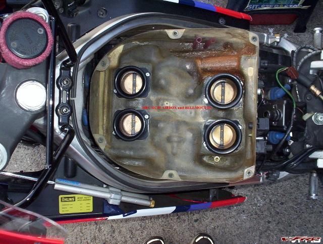
installed a $900.00 HRC air box on his RC45 and saw 120HP on the
dyno... mmmmm... together we wondered if the stock box be modified???
HRC air Box...
Posted Image


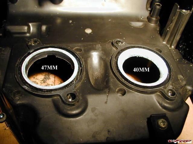
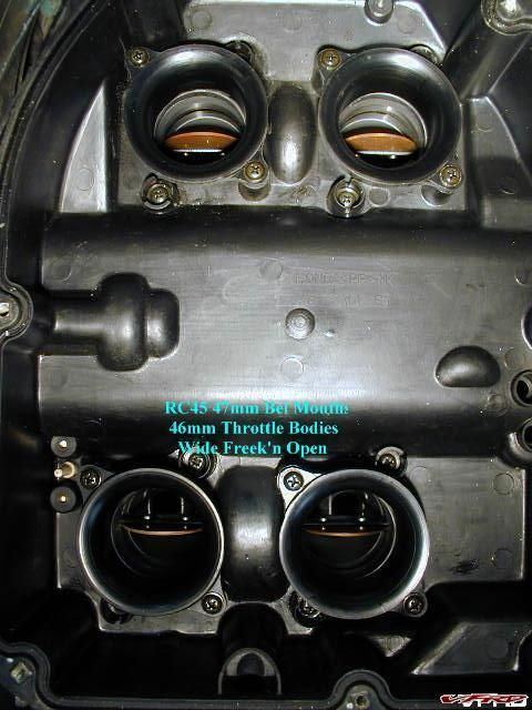
We found that stock RC45 throttle bodies are 46mm but the air box was
restricted to 40mm... no problem... I'll bore the air box out to 47mm
on the milling machine...
Posted Image


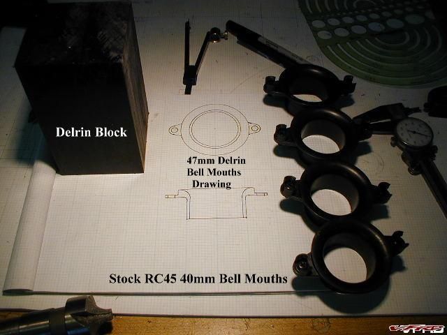
I drew up plans for 47mm bell mouth based on the stock 40mm bell
mouths and purchased a block of black Delrin...
Posted Image


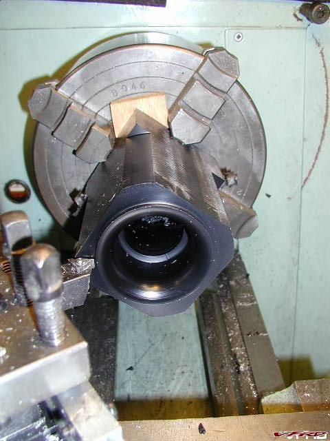
I'm not happy doing repetitious work but I labored long hours to
machine 4 each bell mouths with my best accuracy...
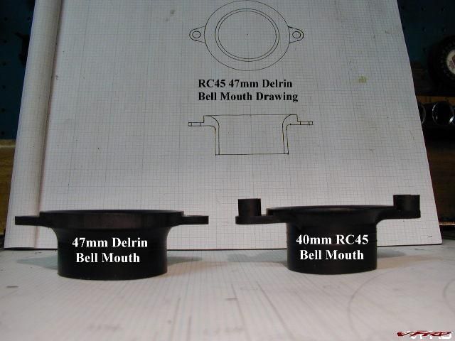
Posted Image


Don't you love when a plan comes together especially if it turns out
perfect???
Posted Image


Now I had an unrestricted air box with my own 47mm bell mouths... it
was the best I could do to replicate HRC $900.00 air box... not to
mention I wanted to keep my home made K&N filter...
Posted Image


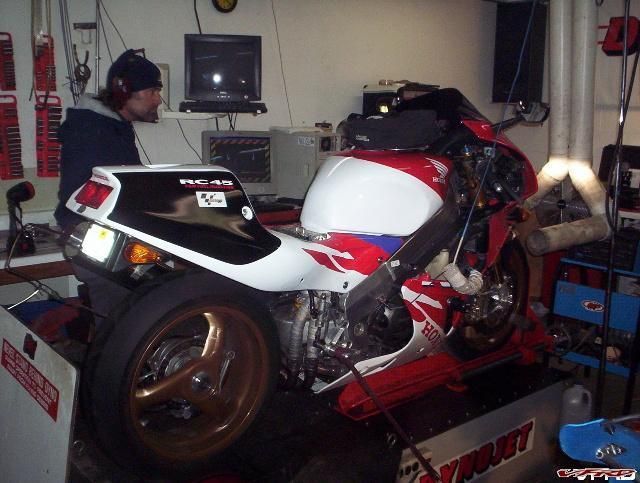
Time to put the Mod to the test... this is Dave at Chandelle
Motorsports...
Posted Image


No joy... I lost 1.8HP on the dyno... so bigger is not better in this
case... a whole week worth of work shot down in flames... it seems
Honda got the intake velocity right for a stock pipe after all... air
boxes are like tuned instruments... alter the holes and the tune
suffers...
[image: Posted Image]
#46
Larry,

Thank you for the air box post. Very educational.

With the porting, polishing and dome work, along with the larger diameter header (38mm v OEM 36mm), do you think a larger intake would be beneficial?


Coderighter and I have PM'd each other to death regarding retro fitting the PC V to the non evap canister model years. Speed and temp mapping is a snap. What I need to do is find a vacuum source to run a switch from in order to turn the Autotune off/on based upon accel/decel.

Keep chiming in please. All info is very welcomed.

More as I get it.
#47

He fixed too many to count, but knew that their failure was due to poor mfg/materials, not as much oiling.


Negative...

Honda great cam shaft crisis wasn't mfg/materials... Honda's great cam
shaft crisis was the result of a factory cost cutting measure... they
choose to mill the cam bearing blocks separately... there was no
matching of components... consequently the cam bearing blocks were not
line bored with the head... if the tolerances happened to add up...
the cam will flop about in the head.. you'll notice the edge of the
cams fail first... a sure sign the cam shaft tilted and was allowed to
strike the follower at an angle... this also explains why some cams go
100K while other only 20K...

Isn't this the definition of using poor MFG/Materials? instead of line boring they milled the blocks in parts....
#48

Larry,

Thank you for the air box post. Very educational.

With the porting, polishing and dome work, along with the larger diameter header (38mm v OEM 36mm), do you think a larger intake would be beneficial?


Opening the front door (air box) along with opening up the back door (larger diameter header) usually needs more than port and polish... I think you'll also may need more compression along with bumpier cams...
#49

Larry,

Thank you for the air box post. Very educational.

With the porting, polishing and dome work, along with the larger diameter header (38mm v OEM 36mm), do you think a larger intake would be beneficial?


Opening the front door (air box) along with opening up the back door (larger diameter header) usually needs more than port and polish... I think you'll also may need more compression along with bumpier cams...

I agree Larry, the cams are key for this motor. If we can find someone to make some relatively inexpensive cams for the 5th gen then all kinds of doors should open.
#50
I'm checking with the EBD to see if the cams can be worked as well.

On another note regarding the PC V for my 98 non Cali model. Coderighter installed a PC V on his 6th gen and also has the Autotune. He has mapped by gear/speed, temp, and has a vacuum switch for turning the Autotune off/on during accel and decel.

We've discovered that the 5th gen wire harness matches along years so I can tap into it for the map by gear/speed and engine temp without issue. The vacuum switch was another story. Coderighter removed his EVAP canister and solenoid and used the vacuum hose to tap into the four vacuum hoses connected to the injectors. On my bike, no such thing, the four hoses die at the airbox and never join each other. So, I'll find a 4 into 1 connector, add a length of hose and drop a vacuum switch onto that. This will solve my vacuum source hunt.

Many thanks to Coderighter for diagnosing my situation.

More as I get it.
#51

I agree Larry, the cams are key for this motor. If we can find someone to make some relatively inexpensive cams for the 5th gen then all kinds of doors should open.


This might be cheaper in the long run... at least you can get your money back and then some...

http://cgi.ebay.com/...e=STRK:MEWAX:IT
#52

I agree Larry, the cams are key for this motor. If we can find someone to make some relatively inexpensive cams for the 5th gen then all kinds of doors should open.


This might be cheaper in the long run... at least you can get your money back and then some...

http://cgi.ebay.com/...e=STRK:MEWAX:IT

Good point, but that one bike will only help the one guy who buys it!
#53

I'm checking with the EBD to see if the cams can be worked as well.

On another note regarding the PC V for my 98 non Cali model. Coderighter installed a PC V on his 6th gen and also has the Autotune. He has mapped by gear/speed, temp, and has a vacuum switch for turning the Autotune off/on during accel and decel.

We've discovered that the 5th gen wire harness matches along years so I can tap into it for the map by gear/speed and engine temp without issue. The vacuum switch was another story. Coderighter removed his EVAP canister and solenoid and used the vacuum hose to tap into the four vacuum hoses connected to the injectors. On my bike, no such thing, the four hoses die at the airbox and never join each other. So, I'll find a 4 into 1 connector, add a length of hose and drop a vacuum switch onto that. This will solve my vacuum source hunt.

Many thanks to Coderighter for diagnosing my situation.

More as I get it.


I have 4 vac hoses out back of my airbox, runs the starter valve (or at least thats where I hook up to balance the starter valve). I do have a Cali bike tho, so YMMV.
#54
More engine info.

Got some pics of the tear down. The cylinder heads are a bit crispy with carbon, as you can see in the photo where he scraped the soot off. Those are the areas where the EBD will add material and "weld it shut". On the cyl that had the bad cam, a bit more carbon as the lobe had been worn to not allow full motion, capturing the burnt gases and not allowing them to escape.

[image: honda vfr 007.jpg]
[image: honda vfr 010.jpg]
[image: honda vfr 003.jpg]
The work on the water pump was more than I first reported. He also milled down the cover to decrease the area. Decreasing the area allows less cavitation.
[image: honda vfr 002.jpg]
Here is a shot of the Autotune sensor. I've located it here as it is the only place that won't foul the suspension linkage, and I can route the harness up and near the driver's peg holder.
[image: VFR 800 PCV O2 002.jpg]
Coderighter and the boys down under have kept up with the PCV testing. Once I get the bung welded on, I too will jump into this. Coderighter was kind enough to assist with the vacuum switch I'll be using to turn the Autotune on and off depending on load/no load.

I can't install the PCV yet as the bike is at the pipe dude for the custom up pipe/ Y to connect to the Laser cans. I hope to have it back mid next week.
#55

Here is a shot of the Autotune sensor. I've located it here as it is the only place that won't foul the suspension linkage, and I can route the harness up and near the driver's peg holder.
<.....>
Coderighter and the boys down under have kept up with the PCV testing. Once I get the bung welded on, I too will jump into this. Coderighter was kind enough to assist with the vacuum switch I'll be using to turn the Autotune on and off depending on load/no load.
I can't install the PCV yet as the bike is at the pipe dude for the custom up pipe/ Y to connect to the Laser cans. I hope to have it back mid next week.

Well I see you are putting the bung in the tail end of the collector. I'm just going to swap out one of my stock o2's for now.
Where did you find the 4 into 1 for the vacuum switch?
I already have the switch from Coderighter, but was waiting on the PC V and autotune to arrive before installing it.
I'm sitting here waiting for my pcv to arrive, and I should have already had the autotune in hand (damm ebay copyright policies).

My underseat area is going to be a solid mass of equipment by the time I get all the stuff installed.
#56

Well I see you are putting the bung in the tail end of the collector. I'm just going to swap out one of my stock o2's for now.
Where did you find the 4 into 1 for the vacuum switch?
I already have the switch from Coderighter, but was waiting on the PC V and autotune to arrive before installing it.
I'm sitting here waiting for my pcv to arrive, and I should have already had the autotune in hand (damm ebay copyright policies).


Coderighter dumped his EVAP system and ran that vacuum plumbing to the switch. The EVAP plumbing is a 4 into 1 with the 1 now being used to link to the switch. On my non-EVAP model, I'm going to unplug those four vacuum hoses that connect to the sides (2 each side) of the airbox, and T those into a 4 into 1. Then I'll run a hose from that to the switch.
#57

Coderighter dumped his EVAP system and ran that vacuum plumbing to the switch. The EVAP plumbing is a 4 into 1 with the 1 now being used to link to the switch. On my non-EVAP model, I'm going to unplug those four vacuum hoses that connect to the sides (2 each side) of the airbox, and T those into a 4 into 1. Then I'll run a hose from that to the switch.


Okay I'm following that. My question was were did you find the 4 into 1 "T"??
Auto parts store or somewhere else??
#58
Might want to try an aquarium store?

Something like this (quick google search of 4 into 1 air hose aquarium)
#59

Okay I'm following that. My question was were did you find the 4 into 1 "T"??
Auto parts store or somewhere else??


Doink! I forgot to mention Coderighter used the old vacuum hose system that connected to the EVAP system. In that system there already was a 4 into 1 T. If you don't have that, I obtained a 4 into 1 from a 6th gen and will use that to tie into the vacuum switch.
#60
Dave Dodge and MegaCycle are still in the cam business.
#61

Might want to try an aquarium store?
Something like this (quick google search of 4 into 1 air hose aquarium)

Yeah I was thinking about something like this 4 into 1 manifold
I just wasn't sure of the sizes, so I was asking what others have used.

I wish that someone had a cut away of the throttle bodies that could show where all air passages enter into the intake tract.
#62

Dave Dodge and MegaCycle are still in the cam business.


Dave Dodge to the rescue :pissed:

I spoke to him this morning and he said he could do some cam work. He finished a 5th gen last year with very good results. That job included a 1 over bore and some other stuff...

I've linked up with my EBD who will contact Dave direct and they'll do their engineering stuff.

Great call Seb. Thank you.
#63

Dave Dodge and MegaCycle are still in the cam business.


Dave Dodge to the rescue :laughing6-hehe:

I spoke to him this morning and he said he could do some cam work. He finished a 5th gen last year with very good results. That job included a 1 over bore and some other stuff...

I've linked up with my EBD who will contact Dave direct and they'll do their engineering stuff.

Great call Seb. Thank you.

And he gets a hot cam?! :pissed:

This thing is going to be a beast when its done! Can't wait to see the final product!
#64
sa1713,

I have not seen it discussed on this thread, and don't know if it is a possibility w/ the VFR, but have you given any thought to lightening the flyweel? Maybe lightening and re-balancing the cam drive gears? It would allow the motor to spin up much quicker/easier :laughing6-hehe:
#65
Yep, the EBD is eyeing all possible details including those you mentioned.

Right now he has some additonal HRC performance information to grind into his melon and spit out a balanced course. The trick he said is to balance all components so that each is complimentary of themselves. Otherwise, he could have bored it out and called it a day.....
#66

Yep, the EBD is eyeing all possible details including those you mentioned.

Right now he has some additonal HRC performance information to grind into his melon and spit out a balanced course. The trick he said is to balance all components so that each is complimentary of themselves. Otherwise, he could have bored it out and called it a day.....


This way also sounds cooler, and therefore he can probably charge WAY more too. :goofy:
#67

Dave Dodge and MegaCycle are still in the cam business.


Dave Dodge to the rescue :goofy:

I spoke to him this morning and he said he could do some cam work. He finished a 5th gen last year with very good results. That job included a 1 over bore and some other stuff...

I've linked up with my EBD who will contact Dave direct and they'll do their engineering stuff.

Great call Seb. Thank you.

Nice work, I'm very interested in seeing the results of all this effort! :fing02:
#68
Latest update.

The EBD is waiting for the cams to return from Dave Dodge.

He is going to lighten the flywheel. I'll have the before and after weight for publication as well as output.

I did a rough routing of the PCV and also soldered on two leads that will allow map by gear and engine temp. Not as hard as I imagined as the locations of the pins were about as obvious as the rising sun.

[image: VFR 800 PCV w Autotune install 002A.JPG] [image: VFR 800 PCV w Autotune install 014.jpg] [image: VFR 800 PCV w Autotune install 015.jpg]

I stuffed the wires into a split loom and ran them to the rear of the subframe for future connection.

I researched some readily available K&N rectangle air elements, looking for something that would fit inside an OEM plate. Alas, I found the elusive Citeron, part number 33-2227 with a thickness of 29mm (about 9mm more than OEM) which provides approximately 40% more filter area.

I cut out the used filter material from an OEM element and I'm awaiting the K&N for final fitment.
[image: VFR 800 Air Element 004.jpg]

Meanwhile, I received a vacuum switch from Jon (Codewriter) that will be used to turn the Autotune on during accelleration and off during decel. First I needed to source a 5 way vacuum terminal and then extend the OEM hoses which terminated on the sides of the lower airbox.
OEM hose location:
[image: VFR 800 Airbox PCV routing 004.jpg]

5 way vacuum hose relocation:
[image: VFR 800 PCV Vacuum Hose 002.jpg] [image: VFR 800 PCV Vacuum Hose 003.jpg]

I've tested the vacuum on and off throttle and the values Jon provided me will work out spot on! The switch he sold me(the same as he's advertising) was simple enough to set and wiring will begin shortly. Awaiting block off plates.....

That's all for now.

More as I get it.

Jim

Attached Images

  • [image: VFR 800 PCV Vacuum Hose 007.jpg]

#69
I'm kind of interested to hear your long term opinion on the lightened flywheel. Normally when you go lighter it makes the motor twitchier, as in it's easier to make quick rpm changes. On our bike, where it's already quite "throttle sensitive", I'll be eager to hear how it runs in "cruise" mode on the highway, or you know, getting to your fun places...

Otherwise, I'm very excited by your entire project, and can't wait to see your results.


And then when you decide to toro-charge it too. :laughing6-hehe:
#71
Yup,  mostly electronics.

I have the complete PCV w/Autotune installed and running.  All of the TPS, Speed, and Gear calibrations completed.  I have the Temp input wired, and it reads voltage from my hand held unit, but the software does not yet recognize it...  I've flashed (not the old lady on the corner) the firmware at least 4 times, so maybe I need to do it 4 more?

The vacuum switch Coderighter sold me works flawlessly to turn Autotune off during decel.

The block off plates were a bit of a bugger to install, but they finally went on.  No leaks yet!

Now on to some data gathering and tweaking.

I'm glad I've installed this package now so when the worked engine arrives, the learning curve will be a bit quicker.

I have an air element mod that I'll have pics soon.  Let's just say a lot more airflow...
#72
Okay,  some pics of the K&N custom filter mod.

First I used an OEM air element and cut out the filter material and spines.  

I then ordered the wrong sized rectangle K&N, and returned it.  Ordered a larger one (K&N part number 33-2629)and voala!  I only needed to fab two spacers (about 3mm each side, the thickness of the OEM ABS rear fender/undertray...)

It pops right into the OEM plate.  Now just a bit of epoxy to secure the spacers and then a final dose of RTV gray (MOTO) which will hold all of it nice and snug.  I researched the use of the gray due to the possibility of petrol fumes eating away at the adheasive.  The gray will withstand petrol.

The custom dimentsions are about 10mm less in length and that much in width, but about +10 on the depth.  Just those figures I'm up about 28% more filter area, and with their better material even more.

[image: VFR 800 Air Element 004.jpg] [image: VFR 800 K&N Filter Mod 001.jpg]
[image: VFR 800 K&N Filter Mod 002.jpg] [image: VFR 800 K&N Filter Mod 003.jpg]
[image: VFR 800 K&N Filter Mod 004.jpg] [image: VFR 800 K&N Filter Mod 005.jpg]
[image: VFR 800 K&N Filter Mod 008.jpg]

Once I get the PCV set, I'll dump this into the airbox and see what happens....

Jim
#74
+1 for DynoJet customer service.

After installing the PCV w/ Autotune on my current motor, I was not receiving all of the information.   A couple of members had to flash their firmware a couple of times before all of the features would work.  So, I reinstalled the new firmware.  Almost immediately I noticed an error code (148 CAN Rx Configuration - Invalid Output Error).

So, I jot that down and call DJ for support.  They recommended that I disable all of the extras and work back from there, since there is no such error code 148....

Today I was able to do a little detective work, only to find that nothing that I disabled/enabled seemed to fix the error code.  Back on the phone and I remember Coderighter talking about live customer serivice, so I pulled up their site.

Doink!  There it was.  After speaking to a live tech dude, he worked through the network and took control of my laptop in order to trouble shoot.  See, I had one lonely fuel table at 8000rpm and 60% throttle that showed -95.  Tech dude tried all he could to fix including another firmware update.  No go.

So, he set me up for a return.  

I'm very pleased with their service.  I'll update once I get the new unit installed.

Jim
#75
Any updates on the build?
:blink:
#76

[image: View Post]sa1713, on 24 June 2010 - 09:32 PM, said:

[image: Attachment] VFR 800 K&amp;N Filter Mod 008.jpg
Jim:

You may want to take the packaging off first tho!   :laughing6-hehe:

Looks really nice.  I may change my UNI foam out for something like you've done.
#77
I'm really interested in the cam development, any news on that?
#78
Sorry for the absence, way too much other "pressing" things to take care of.  

I spoke with my EBD about the everlasting stator and the three phase leads.  He's in the process of determining if he can rewire them with a larger gauge wire.  If he can not do it due to OE manufacturing process, I'm going to check with Custom Rewind in Alabama.  Good Ol' Gary there will be able to determine if that will help with our charging issues.

I believe we are still awaiting the delivery of the cams from Dave Dodge and the end of the racing season.  EBD is ususally inundated with "needed it yesterday" orders.

I'm still fussing with my own electrical deamon as the R/R side of the connection did a bit of melting and I've not had time to repair that eventhough Tightwad hooked me up really well with a custom VFRness.

I hope time will free up after the base and door molding gets installed (yes, I'm becoming a trim carpenter..)
#79
Got a part # for the air filter element you used?
#80

[image: View Post]sa1713, on 24 June 2010 - 09:32 PM, said:

I then ordered the wrong sized rectangle K&N, and returned it.  Ordered a larger one (K&N part number 33-2629)and voala!  I only needed to fab two spacers (about 3mm each side, the thickness of the OEM ABS rear fender/undertray...)

[image: View Post]SEBSPEED, on 13 October 2010 - 11:55 AM, said:

Got a part # for the air filter element you used?

#81
Just wondering how your getting on with the motor? :biggrin:
#82
The EBD inspected the stator and said it looked brand new.  I asked if he could upgrade the 3 phase leads and he said that he could.  So, at least I'm trying to lighten the resistence a bit and combined with Tightwad's VFRness I think It may work out very well.

I believe the EBD is nearing the reassembly portion as all of the cam grinding is complete and the racing season is finished.  I hope to have it back within the next few months.....
#83
I emailed Dynojet to see if the VFR should really use the Autotune AT-200 kit that comes with two O2 sensors since that's what we have.    With one, you're just picking up only two cylinders.
#84

rangerscott69, on 18 November 2010 - 11:11 PM, said:

I emailed Dynojet to see if the VFR should really use the Autotune AT-200 kit that comes with two O2 sensors since that's what we have.    With one, you're just picking up only two cylinders.

Makes sense.

It would "work" with only 2 cyl being sensed, but then you're "ASS-uming" that the other 2 cylinders will be working the same with the same amount of fuel going to them.
#85
I believe the dual Bosch units are set up for HD and that allows them to tune each cyl independently.  Not sure how what would work or if DJ would advise that use.  Best bet would be to just plug the two OEM bungs and drill a common spot.  Not the easiest way, but may work out best.
#86
Something new by now????
#87
Just a small bit.

I spent the majority of the fall getting to know the PCV and how to deal with all of the adjustablity that comes with it.  Just so much flexibility that there is almost too much.  I've installed the PCV (w/ autotune) on my original motor as I want to learn and dial it in before I take delivery and attempt to learn it then.

I'm very glad I saved my pennies to purchase this over a PCIII.  As I get more into the maps(6 total) I realize that eventhough the PCIII was a good tool, the PCV is much better.  Having the ability to map by gear is by far the best upgrade over the PCIII.  Oh, and the temp control feature.  Preset a temperature and you can add/subtract fuel to cool/heat her up.  I'm wondering if we could somehow convert engine temp input to an exhaust gas temp input......

Anyway, my findings on my 98 with a full TBR header along with a custom up pipe into two Laser xtreme cans are that the base DJ maps are way to lean for me.  I'm not particularly interested in MAX HP, rather engine life and smooth operation.  I found the DJ map was too lean around town, spiking the temp of 200 + in the 30-40mph range.  Normal temps would range around 185-195.  

Many thanks to Coderighter(John) for his guidance with my setup.

So I've cut into the AFR tables about -2% and I'm working on those.  The EBD (engine builder dude) reccomended I get close to 12.7.

He's test fitting all parts now as Dave Dodge came through with freshly ground cams.

I'm reworking my custom K&N filter mod as the sealer did not hold as I wanted.  I will be looking at a more sticky adheasive tape this time.

As far as an option to fit a ram system into the airbox area, I'm looking into something like medical splint material.  It comes in sheets (1/16 thick), is easily formed and is rather rigid after applying the setting agent.  

I hope to speak with the EBD this week and get an update.

More as I get it.

Jim
#88

sa1713, on 18 January 2011 - 08:56 PM, said:

As I get more into the I'm reworking my custom K&N filter mod as the sealer did not hold as I wanted.  I will be looking at a more sticky adheasive tape this time.


Hi - Just a curiousity - on the air filter, why didnt you just grab a BMC part? It has more area than the K&N.  --(I'm running one.)

Cool project. Good luck.
#89

mello dude, on 18 January 2011 - 10:53 PM, said:

Hi - Just a curiousity - on the air filter, why didnt you just grab a BMC part? It has more area than the K&N.  --(I'm running one.)

MD,

I calculated the filtered area and came up with the off the shelf rectangle that filled the OEM dimensions, which is almost the complete size of the pan.  I also went with a deeper/longer pleats as that added to the filter area.
#90
Any news? Has your engine been abducted by aliens as an example of how far we have advanced technologically? The world waits breathlessly (Actually, I'm just curious as hell, this thing is gonna be a monster!)
#91
Still very curious about this awesome HP-hunt from an engine who are sucking its own air :)  Was up???


#92
I'm curious as well.  The delay is not with the EBD, but rather with Dave Dodge.  It seems when he moved his operation, he may have lost his mind, and my cams.  I believe they were found and finally faced and ground but that has been the delay.

In this delay, I've been able to learn the PCV to the point where I'm now playing with AFR.  Oh, and my stator crapped out on me too.

I hope to have something good to report in the next few months.

Sorry for the quick burst of excitement and then a long lull.  It is killing me too.

Jim
#93
ALL YOUR CAMS ARE BELONG TO US................
#94

[image: View Post]CornerCarver, on 30 August 2011 - 08:41 PM, said:

ALL YOUR CAMS ARE BELONG TO US................


(groan)  somebody had to do it........     :laughing6-hehe:
#95
:lurk:

I have really been interested in the outcome of this project...
#96
Well,

It looks more and more like Dave Dodge has misplaced all of my cams.  The EBD is still trying to get him to ship them back, with no results.

More in the next few weeks.
#97
Argh. Sounds like he owes you another set!

If I were him, I'd EBAY a set of used cams to replace the ones I'd lost, do the work that was promised, and send them to you, with a significant break on the cam weld/grind pricing. Like at cost.
#98
Wow, that's horrible. Hope it all works out!!
#99
Doink! Dave Dodge found my cams! Oh, and he states that with just the stage one grind, minimum 8HP gain.

At least during this "lull" I've been able to learn the PCV.  I seem to like a smooth fuel map rather than a peak HP map.
#100
Good news
#101
sa1713

Doink! Dave Dodge found my cams! Oh, and he states that with just the stage one grind, minimum 8HP gain.

Cool! :fing02:

#102

So now we are back on track? Did you get any pics of the welded heads? Also i wonder about the spesifics of the came work... weight reduction? Balanced weight? Anything done to the gears?

Did you get the weight shaven of the flywheel?

#103

Yes, back on track for completion. When all of the components are gathered by the EBD, he'll measure and record all the specifications. Flywheel is still on the table for modifying. He does not want to take too much off....

#104

OK so what's happened to this project ?

I'm in the middle of installing my own cams, awaiting shims at the mo, hope to have the bike back on the road next week & then dyno tuned for the new cams (assuming they work OK) with my PC3. Once I have a finished product to show, I'll release the cam info for others to follow if they so desire. Mine took 3 weeks to get, first order, new profile etc, any other orders would take a week !

Hey Larry, thanks for the pics of the RC45 airbox/bellmouths. Interesting that the 5th Gen has the SAME 40mm bellmouth entry to 36mm throttle bodies. I just hand lapped mine to match the throttle bodies as the ID at the base of the bellmouths was only 35mm & another set I have were only 38mm at the entry & 34mm at the base !

For RAMAIR inlet, you can see what I did last year here, it seems to make a difference at speed as the bike was still accerlerating hard at 140mph, which is as fast as i've taken it so far.

http://vfrworld.com/forums/5th-generation-1998-2001/33383-vfr800-5th-gen-10-year-update-project.html

Phase 2+3, will be written up in a couple of weeks time, to cover the upgrades/changes made during the past winter :rolleyes:

Chris W.

#105

Oh forgot one thing, your EBD may be wrong about the oil cooler ! If as he asserts the oil flow is not great then an upside down cooler would crud up with contaminated oil, as the cooler is a sperate circuit to the pressure feed system & pumps oil straight from the sump to the cooler. By being this way up there is no dead space for old oil crud to collect. I think you will find there is easily enough flow to use all the galleries in the cooler.

If you look at my second ramair solution, this increases flow to the cooler & I will add a baffle underneath between the cooler & the cylinder head cover when I put it back together, this will further increase airflow through the cooler due to the baffle causing higher air pressure in front of the cooler & lower air pressure behind it at the same time !

Edited March 22, 2012 by Mohawk
#107

Just a silly question, but if you go to what is effectively a ram air system as opposed to the still air box, how do you expect the motor to behave through the rev range in 1st gear with no real air compression, 3rd gear some air compression, and 6th gear with Max air compression. Careful where you go with your mods.

When my PC was installed, all we did was open up the low speed flap in the air box, change to a hi flow filter, and nothing more. The Dyno showed that it went from a standard 103 hp 76 N-M bike, to 109 hp 79 N-M bike. While this does not sound like a lot, it's where it made the power that counts.

It used to hit 100hp at 10,000 rpm and drop below at 11,250 rpm, now it hits 100hp at 9000 rpm and doesnt drop below untill 12000 rpm. The Torque, which hardly touched 75 N-M at 9000 rpm, now hits 75 at 7000 rpm and stays above 75 untill 10000 rpm. All this leads to a bike which feels so much better through the range where I ride it the most. It just feels a lot more beefed up....

Love that VRF

#109

Racing season is about to finish so I would expect that the EBD will complete this soon.

#110

Well, I don't have good news to report. I've found that Dave Dodge may have fallen down on not only my cam work but many other customers' work. He not only has my cams but also a sizeable deposit. Nothing compared to other customer's experiences. I'm copying a post from another V4 forum which chronicles a complete engine rebuild.

I'm in the process of attempting to recover my parts and $$$....

It seems as though DD was not truthful or forthright in his recent dealings. Here is the post and sorry if this is put in the wrong place. The pics did not come through but I have the complete post if folks need to confirm.

My last posting here at this site was on my thread "Re: Anybody that has an engine at Dave Dodge's... Please look!" it was #61 where I stated "I will wait until after the weekend of the 18th of March before making contact with them as that is the most recent date of completion given to me by DD last Friday. He has a week."

That was Sunday March 11, 2012. The following Friday I received a call from Dave Dodge stating that he had indeed finished my engine and it was ready to be picked up that weekend. I couldn't do that as I have been working weekends for months now. I scheduled the weekend of April 1 off and asked Dave if that would work for him. He responded that that would work and he looked forward to it.

The following is true there is no slander and deceit on my behalf...

I sent Dave a confirmation email this past Wendsday, March 28 at 4:43am, it follows:

Hi Dave,

Just touching base wanting to confirm our upcoming Saturday pick up? We will be getting into Bullhead Friday evening. What time would you like to meet Saturday? Anytime works for me. If need be we can do it Sunday as well...

Please feel free to give me a call or email. Either way, I need to make this happen this weekend as my work schedule is still more than crazy and this is the only time I was able to schedule off...

Thanks!

Steve

salvo66us@yahoo.com

This is the response that I received from Dave that same day at 5:51am, it follows:

Steve,

We are good for Saturday, about 10ish? Looking forward to it :)

Dave Dodge - DRP

-----Original Message-----

From: steve lawrence

Sent: Mar 28, 2012 4:43 AM

To: Dave Dodge , Dave Dodge

Cc: salvo66us@yahoo.com

Subject: Engine pick up...

Hi Dave,

Just touching base wanting to confirm our upcoming Saturday pick up? We will be getting into Bullhead Friday evening. What time would you like to meet Saturday? Anytime works for me. If need be we can do it Sunday as well...

Please feel free to give me a call or email. Either way, I need to make this happen this weekend as my work schedule is still more than crazy and this is the only time I was able to schedule off...

Thanks!

Steve

salvo66us@yahoo.com

Ok, I received a call from Dave Friday morning March 30, everything is a go for Saturdays pick up except that he has to get some orders out and instead of meeting at 10am he wants to do it about 1pm so he can get the orders out to the Post Office... I agreed and we head up to Bullhead from Phoenix, Az. I received a call from Dave Saturday morning, March 31 at 12:16pm stating that he is behind a little bit and still needs to get these orders to the Post office and meet with his accountant and won't be able to meet until about 5pm. I reluctantly agreed. At 4:42pm I received the call from Dave that he had found that he just wasn't happy with how the #2 cylinder bearing was feeling and that he had taken the case back apart and wanted me to see it in person as it would be better to explain the situation to me. I told him that we would be over in just a few minutes to pick up the engine and go from there.

As a witness to what we were going to see and retrieve I had a retired Sheriffs officer tag along, kind of a tool to keep heads level for the moment... I wasn't there to cause problems or curse anybody out... I just wanted my due... My COMPLETED engine that I had waited for for over 2 years.

Upon hearing the excuses as to why he couldn't meet me at the original time scheduled I knew that there was more to the story...

The following pictures were taken as soon as I unloaded the boxes from the vehicle this afternoon once we got back home in Phoenix... This is just an intial set of photos. It will take me days to lay everything out and retake pics that may be needed for whatever legal action comes next. I honestly don't know what to expect at this moment...

I would like to bring to light 2 postings from Dave Dodge in my previous thread, # 71, it reads as follows:

Re: Anybody that has an engine at Dave Dodge's... Please look!

« Reply #71 on: March 12, 2012, 09:38:34 PM »

Quote

I just read all of your posts with interest. I only want to say that in no way has anyone been screwed or ripped off, nor will they be. Assuming the worst tends to be the way of the board. I'll admit that engine building since the move has not been easy and taking far too much time. I dont want to comprimise the level of quality either. If anything can go wrong... it has. I do apologize to Aaron and Steve, and even John. Thank you for your patience and I assure you that getting these projects delivered is more important to me than is realized.

Regards

Dave Dodge - DRP

And also, #79 from Dave as well, it follows:

Re: Anybody that has an engine at Dave Dodge's... Please look!

« Reply #79 on: March 13, 2012, 09:58:51 AM »

Quote

I completely understand all the concerns. It's been busy enough to keep me chasing my tail, but the level of sales is not fully supporting expenses or even cost of parts. I've made numerous changes to correct this. Most engine deposits started off at 50% and became progressive as I purchased the parts and outside labor to complete them. It became obvious that buying discontinued parts at premium+ prices was costing me more than I had them sold for. Labor from the machine shops is costing me $75.00 hr, yet I was only charging $50.00 hr., plus big shipping costs. Added to that, all my suppliers had subtantial and frequent price increases due to their higher costs. Products from Japan (Honda) are seeing 5% increases every time I order due to dollar to yen conversion. The slow economy and higher energy prices contribute to this as well.

I refused to increase the prices on those firm quoted jobs, but in the future engine jobs will be termed as 'restorations' and billed time and materials. Needless to say, engine building volume will be reduced, but if there's no profit in doing them, maybe that's best. The whole engine building side of the business has been causing me big concern... mostly due to the length of time to complete. I have never been known as the speediest engine builder, but I dont have comebacks either... it's gotta be right, and that's how I think my reputation developed. When talking directly to my customers, I do my best to explain the circumstances and reasons for the delays...

With all that said... I am (and have been) in this for the long haul, and the bumps in the road are a huge learning curve, even at age 56 with 30 years experience working on V4's.

Looking forward to a better tomorrow,

Dave Dodge - DRP

The pics...

This is the COMPLETED engine:

A pic of one of the pistons showing what looks like used rings on it, next to it is a ring from the bundle of "old" rings found laying in the boxes...

A pic of a scratch in what looks like the #1 piston crank journal bearing...

The box the bundle of rings were in...

Here is a pic of my $560.00 HardWelded Rocker Arms...

And another...

My cylinder heads... They were supposed to have Stage 2 Porting, Smoothing the intake runners and a Competition Valve Job, The tune of $400.00...

Doesn't look like any smoothing or valve job was ever done...

Boxes of head and valve parts... I must add that Dave was witnessed as grabbing "Valves" out of a plastic bag that he picked up from underneath a bench and added these valves to my parts. You can notice that there are valves that have been ground and valves that have not... The ground valves were from the plastic bag... I don't know if they belong to someone else's "valve job" and he just grabbed them to add to the mix or ???

My carbs were to have been cleaned and rebuilt to Stage 2, at $325.00 labor and parts kit... Dave was witnessed as removing parts from a set of carbs other than mine and adding these to my parts. There again I don't know if these pieces belonged to someone else's carb set or ???

I did realize that in the hulabaloo that he still has my airbox and rubber venturis.... Fat F'n chance of getting that stuff now!

The trans was to have been "undercut" at $375.00... it looks like it was glass beaded at best... I don't know what to look for in an under cutting job but I can't see any fresh machining marks, maybe one of you can help me to spot it...

My cases were to have been powder coated... None of this has happened. It wasn't on the work order but he was paid $150.00-200.00 for that service. Supposedly he has a new work order that he is going to email me... He did however "paint" the oil pan and shift cover, and maybe the engine case...

I didn't even get the one hole that I asked to have "helicoiled" taken care of...

The date on this gasket set should have been from way before 9/16/2011... Should have been back in 2010 when I was originally supposed to be picking up my engine in December 2010.

The gasket set and an, I think, oil pump...

Just a couple of random pics...

I am speechless........... I do not even now where to start......... My restoration project is done.

I have paid this man $4500.00 overall and this is what the culmination of more than 2yrs waiting and more than numerous emails and phone calls have gotten me. All the way up 'til the very end has been nothing but an excuse and as far as I am concerned, lies!

I don't know what is going to happen but I will be getting in touch with the Arizona Attorney Generals office and see what is next. I am posting this because I HOPE that I can at least save someone the future hassles and trouble in which they may find by doing business with this man. I have certainly learned a very costly lesson here. I have somewhere around $7-8000.00 wrapped up in what was to be a "Better than New" restoration of my dream bike. This has all been crushed now.

I can't speak here how I really feel and what I would really like to do.... I am sickened!

Dave, I am certainly glad that you have clearly stated that " I only want to say that in no way has anyone been screwed or ripped off, nor will they be."

#111

Sorry to hear that your ebg has let you down that badly. I'm an ex mechanic & I hate giving anything to anyone to do stuff for me but sometimes it's the only option & sometimes my worst fears are realised as in your experience. I can imagine how you feel, I'd be gutted beyond belief.

I hope you find a solution soon. Good luck.

#112

Sad story. This happens all to often in the performance industry. Cycles, cars, dragsters, you name it. It shows that lots of people have trusting souls. That is better than being an all out cynic. The difficult part is knowing when to cut your losses and retrieve your stuff. In the hotrod world a few years ago, United Speedometer came to light in a negative way. People lost their obsolete speedos with no way of retrieving them. I'd hate to be the guy doing a restoration and having the only one of something and having a business rob me of my property. My sympathies to all who lost out with this guy.

#113

i went through a similar experience with my Thruxton. It took me almost a year and the local sheriff to stop by the engine tuner's house 3 times and threaten to lock him up if he didn't ship me my cylinder head back. Just a simple port and polish! The guy had duped many others besides me. Somehow I got lucky and the local sheriff took my complaint seriously-(stolen property, I had receipts to prove that they were sent to him).

I have come to realize that for every good, ethical engine tuner out there, there are about 5 bad ones. The same goes for painters. From now on if I can't stop by and talk to the guy face to face myself, I won't be shipping my parts out to them.

Fortunately I have not had that experience with suspension tuning. I have shipped shocks/ forks to specialits like Thermosman and at Ohlins and never even remotely had an issue.

#114
MohawkSorry to hear that your ebg has let you down that badly.

My original EBD is perfect, the hang up is with Dave Dodge. He has my cams, which in the big scheme of things is easily replaceable and that is in process. I have complete faith in Craig and his operations but I do agree with putting a hand on the trades and keeping an eye on them as well.

I hope to have good news shortly.

#116

I've got a rather good update:

After reading the posting about DD and the customer's experience, I did not hold much hope of getting my cams back or my deposit. I made repeated attempts to contact DD with no success. So, I found a complete set of 4 cams from a 98 and had them shipped to my EBD in anticipation of a DD failure.

While the cams were in shipment, I was able to get Dodge on the phone. He gave me an excuse that he had not been notified by his grinder that the job was complete. I, being suspect of his response, gave him some more rope. He told me that the grinder needed to build a fixture to hold the cams since he did not want the gear removed during processing. Dodge told me that taking the gear off causes a whole bunch of headaches during reassembly, many times unsurmountable. He did admit that he has had the cams much too long for no progress and was apologetic. Yeah, I've heard that somewhere before...

In my attempt to elicit additional information that I could possibly use (against him) in the future, I asked where he sent his cams to be ground. I did not expect him to answer, as his pause was long. He did answer, and it was:

&amp;nbsp;

Veefer800Canuck

Personally I would deal with WebCam or someone like that who is well established in the industry.

&amp;nbsp;

Dodge told me he expected Webcams to give him an update within a week or so.

I thanked him for his time and told him I'd call in a week.

I immediately called Webcams and spoke with customer service. They had no idea of a cam job for a VFR800 but said they would call me back. About 10 minutes after hanging up I received a call from Dodge who told me that the cams would be finished in 1 week. I believe Webcams called Dodge and told him that I called. I never received a call back from Webcams.

Dodge told me he would get the cams from Webcams and then ship them to my EBD. I asked him to drop ship them directly to Craid at HRT. He agreed but would have to work out the numbers between Webcams etc...

A week later and no word from Dodge. Finally after 5 days of calls and messages he answered saying he spoke with Craig and they settled on cost. I called Webcams to confirm and they said they are ready to ship and I asked for the cam card to be included.

I expect to have the cams ready for install within two weeks but I'm still holding my breath.

When Craig receives my cams he will be documenting the work, and determining if they will do what he specified.

If/when this project gets finished, at least we have a direct source to have 5th/6th gen cams ground.

I will publish the cam card once I get it.

v/r

Fingers Crossed.....

#118

That is good news...it was looking bad for the home team for a while.

#119

We are all waiting for the fat lady singing the blues on this one.....

#120
Dutchy

We are all waiting for the fat lady singing the blues on this one.....

Nah. Something more upbeat.

How about When the Saints go Marching in? :wink:

#121

March is in. Don't know about the saints. How's the project?

#122

Nice one...took me a minute, great time for a page change.

#123

Well, DD was not completely forthcoming with his actions. In January I spoke to him and he told me the cams were at Webcams for grinding. He was waiting for them to build a fixture to hold the cams without the need to remove the gear. He assured me that Webcams finally was able to accomplish this and the process was well underway.

I requested that DD drop ship the cams directly from Webcams to HRT, thus I'd hope to keep my money and the cams from being in his possession at the same time. He agreed and set it up with Webcams and HRT. Well, he did get the remaining amount to complete the job and we waited for Webcams to finish. He again assured me Webcams had my cams.

It turns out that DD never sent the cams to Webcams. On February 6, they received them from DD.

I hope to have news within a week or so about the work done by Webcams. Please be wary of DD and his operation. Next time, I'll cut him out of the deal and go directly to a grinder. At least I'll have the cam card..... I hope!

#125

Will be interesting to see how this turns out. I picked up a used motor this weekend to swap in to my bike and am starting to think about rebuilding the original 85K motor. It would be a long term project but not as long as DD would take. I'll have to see about swapping 49 state cams in to a CA motor with ECU swap and addition of a PC.

Jim, are you doing anything with the pistons, rebore or new rings? I'd guess being such a low mileage motor it's still fresh.

#126

Nothing to be done with the pistons or rings.  They are in perfect shape.  Engine had about 3k miles on it before I got my hands on it.  Craig at HRT (Chico, CA) said a rod/piston swap with lighter bits would not be noticed by me.  He said he could do it, but the money would not be well spent.  I wanted to stay within the original cylinder walls, and not bore it out.  Craig has an extra set of 49 stater cams in his shop now as I found them in the event DD crapped out.  If I ever get mine back from Webcams, you have first dibs.


#127
Whooooooo :) things are comming together i take it :)
#129

Any updates??

I've been also curious on how thing are going for you sa1713.... 


#130
I suppose this one went ahead and died, courtesy of dave dodge...
This is really sad. This is surely the most interesting mod ever ever documented, and documented well by a guy who really raised hig hopes for mankind and the vfr... so so sad...
#131

I spoke with my EBD who said he is working on the heads now.  All other bits are ready as he is finalizing the heads. 

:cheerleader:   :cheerleader:   :cheerleader:  

#132
Finally!!!
#133

bump, updates?

#134
I will go ahead and give this a bump again to see what falls out of the tree :)
#135

Just got off the phone with Craig.  Yes, we are in the last stage.

Craig is completing the final head work, one bank is completed and he's final measuring the second.  Once that is complete he will check the valves and reassemble.  I hope to hear more in 2 weeks.

Fingers crossed.

#136
Oh the exitement :) I really can't wait to hear where the vfr engine can be improved and what the results are after modification!
#137

Cant wait!

Meanwhile,

Tyga Vfr800 Headers/URL] this should be ready for you by then :)

Everything needs boost!

#138
sa1713

Just a bunch of other "world" stuff going on and this project has taken a back seat.

Sorry to keep folks hanging, but life does tend to interrupt our best plans.

Sooo true.... :unsure:

#139

Still struggling with life ? :)

Sent fra min SM-N910F via Tapatalk

#140

Rollercoaster ride of a thread. Though been there with my nsr. Bump!

#141

2017 bump ?

Sent fra min SM-N910F via Tapatalk

#143

Dito,   gota say something here to keep track of a interesting thread.  On a side note, Yep, still working with the ins-outs of the header.  I have more to dos,  I ain't done.

#144

WSS and all, sorry for the delay of delays.  The gasket kit was ordered two weeks ago so I imagine it will be back together soon.....

Pickup will be another story as my local connect may not be an option.  Once I have my hands on the package, I'll update then.  Yes, sorry for the teasers and delays.

#145

It's all good.  I know all to well how these kinds of projects go. 

#146

Holy shit, this is still dragging on? 

Wow, it better be worth it in the end! 

#147

A typical water pump wastes energy by cavitating at high rpms and may pump less water at high rpm.  An electric water pump is not driven to cavitations and can supply more water.   

#148

Good news!  I have the engine back from Hanson Racing Technology, Craig Hanson, in Chico, CA.  I made a trip recently to ship it back east.  Forward Air is about as easy to deal with as my brushless automatic car wash.  No issues.

Here are the build details:

Mild cam hard face and grind by Web Cams  (Don't ever use Dave Dodge.  PM me and I'll explain)

Intake and exhaust ports ported/polished.  Valves and seats ground.  Exhaust ports ceramic coated

Water pump cover modified and ported to allow better flow

Air intake funnels ground to match throttle body intake diameter

Counter sprocket bolt cover (keeps rust/dust off the splines)

A shift star and detent arm was installed as well as a new Custom Rewind stator.  New SAMCO hoses/clamps will go on too.

I'm in the process of gathering all the necessary bits for the swap.  I have a spare frame (salvaged) that was turned into a three legged mare which the original engine will hang in while I decide what to do with it.

I'm not sure what the results will be, but I'll get it to a dyno and post the results.

[image: IMG_8294.JPG]

[image: IMG_8295.JPG]

[image: IMG_8311.JPG]

#149

Looking good.

id be interested to see what was actually done to the water pump cover. 

Any chance you could take a picture?

#150

Sweeet !!!  and Congrats.   Yes,  I'll second the water pump thingy too.

#151

Hey, Chico's not too far from me. I'll have to Google the shop and bookmark it. I'm curious about the dyno and definitely interested in the water pump mod as well.

#152

Best pics I could achieve of the water pump.  Not sure how much was done to the fins, but he cleaned up the inside of the cover.

Craig is a super easy person to deal with.  He is a very honest chap even when presented with an open checkbook.

Cooling system is removed.  Next will be the header, swingarm pivot bolt, and remaining frame mounts. 

[image: IMG_8314.JPG]

[image: IMG_8316.JPG]

#153

Really cool to see some progress here! Happy for you and excited to see some dyno results!

#154

Injector RX received my injectors today, and they already completed the cleaning/refurb.  They ship back tomorrow.  Now, I sent the 8, hoping to get a good set of 4.  Well, all 8 are now back to factory spec.  Anybody in need of 4 factory new injectors?

#156
47 minutes ago, SEBSPEED

If they were 6th gen... 

I might be able to accommodate you. PM Sent.

#157

Blimey, and I thought it must be vapor ware :)

Get it in a bike & get it running. Check out my mods since this first started, up to 120whp with induction & exhaust mods. I went with an electric water pump, much simpler.

#158
1 hour ago, Mohawk

Blimey, and I thought it must be vapor ware :)

Get it in a bike & get it running. Check out my mods since this first started, up to 120whp with induction & exhaust mods. I went with an electric water pump, much simpler.

Hi, which pump did you use? How was the install? Easy, totally custom? Please let me know.

#159

Great project and tenacity  :beer:

Here's something to aim for then....

[image: IMAG6773.thumb.jpg.5dd7fac5ac9ee6a7a3a5a84b2dea6bfe.jpg.27ea4cb7daf49b07370371c9923192c6.jpg]

:goofy:

#160

^ No wonder they are so much fun to ride.

#161
4 hours ago, Dutchy

Great project and tenacity  :beer:

Here's something to aim for then....

[image: IMAG6773.thumb.jpg.5dd7fac5ac9ee6a7a3a5a84b2dea6bfe.jpg.27ea4cb7daf49b07370371c9923192c6.jpg]

:goofy:

Sort that top end fuelling out & you have another 3-5hp for free ! :)

End of thread · 161 posts recovered Wayback Machine snapshot 19 Jan 2022